ABSOLUTE MAXIMUM RATINGS
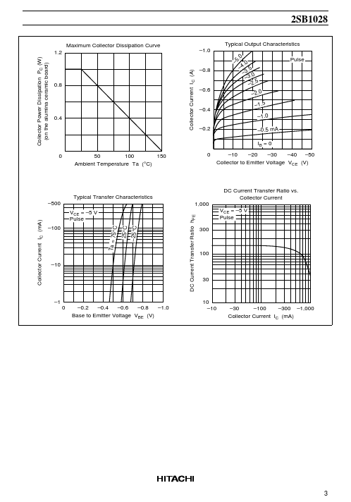
(Ta = 25°C) Item Collector to base voltage Collector to emitter voltage Emitter to base voltage Collector current Collector peak current Collector power dissipation Junction temperature Storage temperature Symbol VCBO VCEO VEBO IC iC(peak)* PC * Tj Tstg 2 1 Ratings –180 –160 –5 –1.5 –3 1 150 –55 to +150 Unit V V V A A W °C °C Notes: 1. PW ≤ 10 ms, Duty cycle ≤ 20% 2. Value on the alumina ceramic board (12.5 × 20 × 0.7 mm) ELECTRICAL CHARACTERISTICS
(Ta = 25°C) Item Collector to base breakdown voltage Collector to emitter breakdown voltage Emitter to base breakdown voltage Collector cutoff current DC current transfer ratio Symbol V(BR)CBO V(BR)CEO V(BR)EBO I CBO hFE1* hFE2 Collector to emitter saturation voltage Base to emitter voltage Note: Mark hFE1 VCE(sat) VBE 1 Min –180 –160 –5 — 60 30 — — Typ — — — — — — — — Max — — — –10 200 — –1.0 –0.9 Unit V V V µA Test conditions I C = –1 mA, IE = 0 I C = –10 mA, RBE = ∞ I E = –1 mA, IC = 0 VCB = –160 V, IE = 0 VCE = –5 V, IC = –0.15 A, pulse VCE = –5 V, IC = –0.5 A, pulse V V I C = –0.5 A, IB = –50 mA, Pulse VCE = –5 V, IC = –0.15 A, pulse 1. Hitachi