2SC5812
2SC5812 is NPN TRANSISTOR manufactured by Hitachi Semiconductor.
Features
- High power gain, Low noise figure at low power operation: |S21| = 17 d B typ, NF = 1.0 d B typ (VCE = 1 V, IC = 5 m A, f = 900 MHz)
Outline
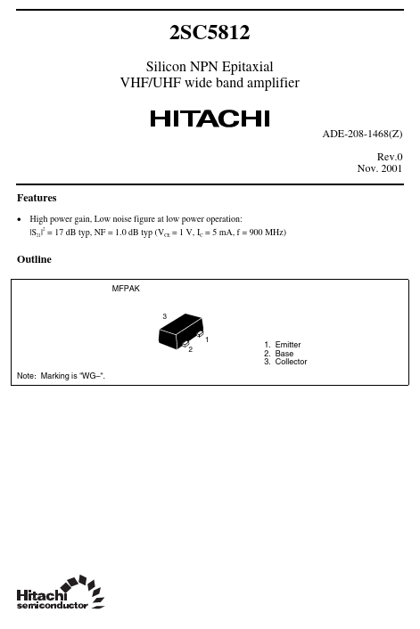
MFPAK
3 1 2
1. Emitter 2. Base 3. Collector
Note: Marking is “WG- “.
Absolute Maximum Ratings
(Ta = 25°C)
Item Collector to base voltage Collector to emitter voltage Emitter to base voltage Collector current Collector power dissipation Junction temperature Storage temperature Symbol VCBO VCEO VEBO IC PC Tj Tstg Ratings 15 4 1.5 50 80 150
- 55 to +150 Unit V V V m A m W °C °C
Electrical Characteristics
(Ta = 25°C)
Item Collector to base breakdown voltage Collector cutoff current Collector cutoff current Emitter cutoff current DC current transfer ratio Reverse transfer capacitance Collector output capacitance Gain bandwidth product Gain bandwidth product Forward transmission coefficient Noise figure Symbol V(BR)CBO ICBO ICEO IEBO h FE Cre Cob f T(1) f T(2) |S21| NF
Min 15 100 8 14
Typ 120 0.2 0.4 11 15 17 1.0
Max 0.1 1 0.1 150 0.7 1.7
Unit V µA µA µA p F p F GHz GHz d B d B
Test conditions IC = 10 µA, IE = 0 VCB = 15 V, IE = 0 VCE = 4 V, RBE = Infinite VEB = 0.8 V, IC = 0 VCE = 1 V, IC = 5 m A VCE = 1 V, Emitter ground, f = 1 MHz VCB = 1 V, IE = 0, f = 1 MHz VCE = 1V, IC = 5 m A VCE = 1V, IC = 20 m A VCE = 1 V, IC = 5 m A, f = 900 MHz VCE = 1 V, IC = 5 m A, f = 900 MHz, ΓS = ΓL = 50 Ω
Rev.0, Nov. 2001, page 2 of 10
Collector Power Dissipation Curve Typical Output Characteristics
180 µ
Collector Power Dissipation PC (m W)
160 µA
140 µA
120 µA
80 60
Collector Current IC (m A)
100 µA
80 µA
60 µA
40...