HMC614LP4E
HMC614LP4E is RMS And Peak To Average Power Detector manufactured by Hittite Microwave Corporation.
.. v03.0109
HMC614LP4 / 614LP4E
RMS & Peak to Average Power Detector 0.1
- 3.9 GHz
Typical Applications
The HMC614LP4(E) is ideal for:
- Log
- > Root-Mean-Square (RMS) Conversion
- Received Signal Strength Indication (RSSI)
- Transmitter Signal Strength Indication (TSSI)
- RF Power Amplifier Efficiency Control
- Receiver Automatic Gain Control
- Transmitter Power Control
Features
IPWR Output: Instantaneous Power, Crest Factor Measurement RF Signal Wave shape & Crest Factor Independent Supports Controller Mode [1] ±1 d B Detection Accuracy to 3.9 GHz Input Dynamic Range: -57 d Bm to +15 d Bm +5V Operation from -40°C to +85°C Excellent Temperature Stability Power-Down Mode 24 Lead 4x4mm QFN Package: 9 mm2
POWER DETECTORS
- SMT
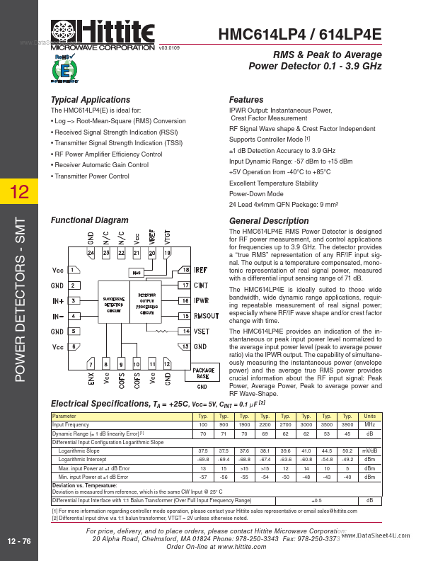
Functional Diagram
General Description
The HMC614LP4E RMS Power Detector is designed for RF power measurement, and control applications for frequencies up to 3.9 GHz. The detector provides a “true RMS” representation of any RF/IF input signal. The output is a temperature pensated, monotonic representation of real signal power, measured with a differential input sensing range of 71 d B. The HMC614LP4E is ideally suited to those wide bandwidth, wide dynamic range applications, requiring repeatable measurement of real signal power; especially where RF/IF wave shape and/or crest factor change with time. The HMC614LP4E provides an indication of the instantaneous or peak input power level normalized to the average input power level (peak to average power ratio) via the IPWR output. The capability of simultaneously measuring the instantaneous power (envelope power) and the average true RMS power provides crucial information about the RF input signal: Peak Power, Average Power, Peak to average power and RF Wave-Shape.
Electrical Specifi cations, TA = +25C, Vcc= 5V, CINT = 0.1 μF [2]
Parameter Input Frequency Dynamic Range (± 1 d B linearity Error) [1] Differential Input Configuration Logarithmic Slope Logarithmic Slope...