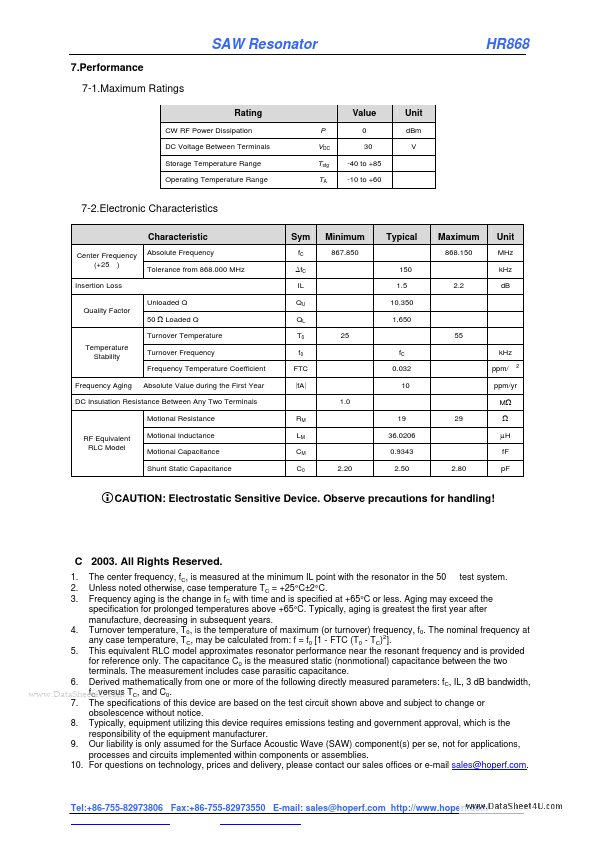
MAXIMUM RATINGS
Rating CW RF Power Dissipation DC Voltage Between Terminals Storage Temperature Range Operating Temperature Range P VDC Tstg TA HR868 Value 0 30 -40 to +85 -10 to +60 Unit dBm V 7-2.Electronic Characteristics Characteristic Center Frequency (+25 ) Insertion Loss Unloaded Q Quality Factor 50 Ω Loaded Q Turnover Temperature Temperature Stability Turnover Frequency Frequency Temperature Coefficient Frequency Aging Absolute Value during the First Year Absolute Frequency Tolerance from 868.000 MHz Sym fC ∆fC IL QU QL T0 f0 FTC |fA| Minimum 867.850 Typical Maximum 868.150 Unit MHz kHz 150 1.5 10,350 1,650 25 fC 0.032 10 1.0 55 2.2 dB kHz ppm/ 2 ppm/yr MΩ DC Insulation Resistance Between Any Two Terminals Motional Resistance RF Equivalent RLC Model Motional Inductance Motional Capacitance Shunt Static Capacitance RM LM CM C0 19 36.0206 0.9343 2.20 2.50 29 Ω µH fF 2.80 pF CAUTION: Electrostatic Sensitive Device. Observe precautions for handling! C 2003. All Rights Reserved. The center frequency, fC, is measured at the minimum IL point with the resonator in the 50 test system.