IMP527
IMP527 is SINGLE CELL BATTERY POWERED ELECTROLUMINESCENT LAMP DRIVER/INVERTER manufactured by IMP Inc.
Features
N Wide operating voltage range
- from 0.9V to 2.5V N Simple design requires few passive ponents N 180V peak-to-peak typical AC output voltage N Adjustable output frequency controls lamp color and power consumption N Adjustable converter frequency minimizes circuit power consumption N Disable mode extends battery life N Disable current 1µA typical N pact Micro SO package option
Applications
N N N N N N N Audio/TV remote control units Pagers/Cellular phones PDAs Clocks and radios Portable GPS receivers LCD modules Toys
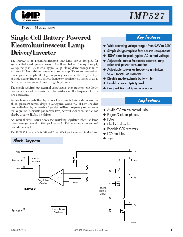
Block Diagram
VDD 1
LX CS
RSW-OSC GND
Switch Oscillator
+
C Regulation Control
Q 7 VREF Bridge Output Driver Q 6 VB Q V A
- IMP527
REL-OSC
Lamp Drive Oscillator
527_01.eps
© 2000 IMP, Inc.
408-432-9100/.impweb.
Pin Configuration
SO/Micro SO
VDD RSW-OSC CS LX 1 2 3 4 IMP527 8 7 6 5 REL-OSC VA VB GND
527_02.eps
Ordering Information
Part Number
IMP527EMA IMP527ESA IMP527/D- IMP527/D1-
- Input Voltage
0.9V to 2.5V 0.9V to 2.5V 0.9V to 2.5V 0.9V to 2.5V
Regulated Output Voltage
YES YES YES YES
Temperature Range
- 40°C to +85°C
- 40°C to +85°C 25°C 25°C
Pins-Package...