International Rectifier IRF7456
Power MOSFET
| Part No. | IRF7456 |
|---|---|
| Datasheet | IRF7456 Download |
| Manufacturer |  International Rectifier |
| Description | Power MOSFET |
| Buy | Stock & Price |
APPLICATIONS
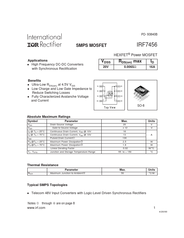
High Frequency DC-DC Converters with Synchronous Rectification VDSS 20V RDS(on) max 0.0065Ω ID 16A Benefits Ultra-Low RDS(on) at 4.5V VGS l Low Charge and Low Gate Impedance to Reduce Switching Losses l Fully Characterized Avalanche Voltage and Current l S S S G 1 8 A A D D D D 2 7 3 6 4 5 T o p V ie w SO-8ABSOLUTE MAXIMUM RATINGS
Symbol VDS VGS ID @ TA = 25°C ID @ TA = 70°C IDM PD @TA = 25°C PD @TA = 70°C TJ , TSTG Parameter Drain-Source Voltage Gate-to-Source Voltage Continuous Drain Current, VGS @ 10V Continuous Drain Current, VGS @ 10V Pulsed Drain Current Maximum Power Dissipation Maximum Power Dissipation Linear Derating Factor Junction and Storage Temperature Range Max. 20 ± 12 16 13 130 2.5 1.6 0.02 -55 to + 150 Units V V A W W W/°C °C Thermal Resistance Parameter RθJA Maximum Junction-to-Ambient Max. 50 Units °C/W Typical SMPS Topologies l Telecom 48V Input Converters with Logic-Level Driven Synchronous Rectifiers Notes through are on page 8 1 4/20/00 IRF7456 Static @ TJ = 25°C (unless otherwise specified) Parameter Drain-to-Source Breakdown Voltage ∆V(BR)DSS/∆TJ Breakdown Voltage Temp.