IXFH150N15P
Features z z
Maximum Ratings 150 150 ± 20 ± 30 150 75 340 60 80 2.5 10 V V
V V A A A A m J J V/ns
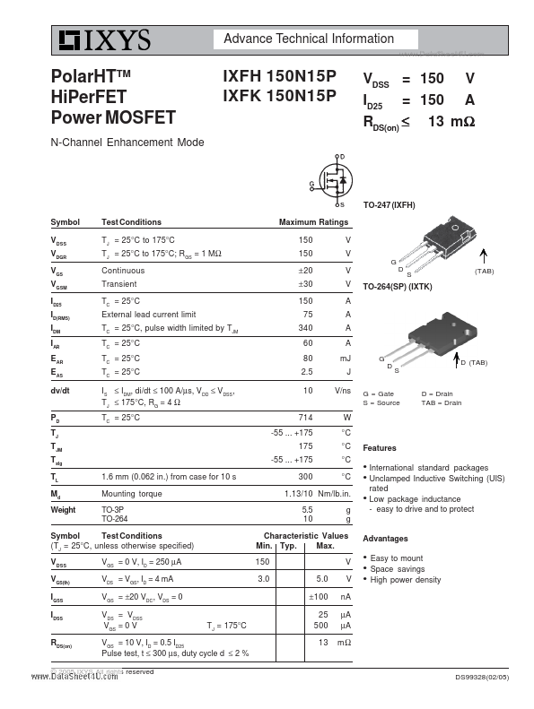
(TAB)
TO-264(SP) (IXTK)
D (TAB) S D = Drain TAB = Drain
G = Gate S = Source
1.13/10 Nm/lb.in. 5.5 10 g g z
International standard packages Unclamped Inductive Switching (UIS) rated Low package inductance
- easy to drive and to protect
Symbol Test Conditions (TJ = 25°C, unless otherwise specified) VDSS VGS(th) IGSS IDSS RDS(on) VGS = 0 V, ID = 250 µA VDS = VGS, ID = 4 m A VGS = ±20 VDC, VDS = 0 VDS = VDSS VGS = 0 V TJ = 175°C
Characteristic Values Min. Typ. Max. 150 3.0 5.0 ±100 25 500 13 V V n A µA µA mΩ
Advantages z z z
Easy to mount Space savings High power density
VGS = 10 V, ID = 0.5 ID25 Pulse test, t ≤ 300 µs, duty cycle d ≤ 2 %
© 2005 IXYS All rights reserved
DS99328(02/05)
TO-247 AD Outline Symbol Test Conditions Characteristic Values (TJ = 25°C, unless otherwise specified) Min. Typ. Max. 55 80 5800 VGS = 0 V, VDS = 25 V, f = 1 MHz 1730 400 30 VGS = 10 V,...