IXGA20N120B3
IXGA20N120B3 is GenX3 1200V IGBT manufactured by IXYS.
Preliminary Technical Information
Gen X3TM 1200V IGBT
IXGA20N120B3 IXGP20N120B3
VCES = 1200V IC90 = 20A VCE(sat) ≤ 3.1V
High Speed Low Vsat PT IGBTs 3-20 k Hz Switching
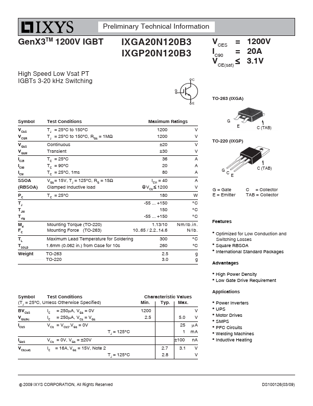
TO-263 (IXGA)
Symbol VCES VCGR VGES VGEM IC25 IC90 ICM SSOA (RBSOA) PC TJ TJM Tstg Md FC TL TSOLD Weight
..net
Test Conditions TJ = 25°C to 150°C TJ = 25°C to 150°C, RGE = 1MΩ Continuous Transient TC = 25°C TC = 90°C TC = 25°C, 1ms VGE = 15V, TJ = 125°C, RG = 15Ω Clamped Inductive load TC = 25°C
Maximum Ratings 1200 1200 ±20 ±30 36 20 80 ICM = 40 @VCE ≤ 1200 180 -55 ... +150 150 -55 ... +150 V V V V A A A A V W °C °C °C Nm/lb.in. N/lb. °C °C g g
G E C (TAB)
TO-220 (IXGP)
C (TAB) C E
G = Gate E = Emitter
C = Collector TAB = Collector
Mounting Torque (TO-220) Mounting Force (TO-263)
1.13/10 10..65 / 2.2..14.6 300 260 2.5 3.0
Features z
Maximum Lead Temperature for Soldering 1.6mm (0.062 in.) from Case for 10s TO-263 TO-220 z z
Optimized for Low Conduction and Switching Losses Square RBSOA International Standard Packages
Advantages z z
High Power Density Low Gate Drive Requirement
Symbol Test Conditions (TJ = 25°C, Unless Otherwise Specified) BVCES VGE(th) ICES IGES VCE(sat) IC IC = 250μA, VGE = 0V = 250μA, VCE = VGE TJ = 125°C
Characteristic Values Min. Typ. Max. 1200 2.5 5.0 25 1 ±100 TJ = 125°C 2.7 2.8 3.1 V V μA m A n A V V
Applications z z z z z z z
VCE = VCES,VGE = 0V VCE = 0V, VGE = ±20V IC = 16A, VGE = 15V, Note 2
Power Inverters UPS Motor Drives SMPS PFC Circuits Welding Machines Inductive Heating
© 2009 IXYS CORPORATION, All Rights Reserved
DS100126(03/09)
IXGA20N120B3...