IXGR60N60C2D1
IXGR60N60C2D1 is IGBT manufactured by IXYS.
- Part of the IXGR60N60C2 comparator family.
- Part of the IXGR60N60C2 comparator family.
..
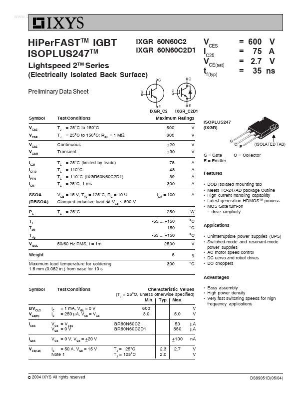
Hi Per FASTTM IGBT ISOPLUS247TM
Lightspeed 2TM Series
IXGR 60N60C2 IXGR 60N60C2D1
(Electrically Isolated Back Surface)
Preliminary Data Sheet
IXGR_C2 IXGR_C2D1
VCES IC25 VCE(sat) tfi(typ)
= 600 V = 75 A = 2.7 V = 35 ns
Symbol V CES VCGR VGES VGEM IC25 IC110 IF110 ICM SSOA (RBSOA) PC TJ TJM Tstg VISOL Weight
Test Conditions TJ = 25°C to 150°C TJ = 25°C to 150°C; RGE = 1 MΩ Continuous Transient TC = 25°C (limited by leads) TC = 110°C TC = 110°C (IXGR60N60C2D1) TC = 25°C, 1 ms VGE = 15 V, TVJ = 125°C, RG = 10 Ω Clamped inductive load @ VCE ≤ 600 V TC = 25°C
Maximum Ratings 600 600 ±20 ±30 75 48 39 300 ICM = 100 250 -55 ... +150 150 -55 ... +150 V V V V A A A A A
ISOPLUS247 (IXGR)
(ISOLATED TAB)
G = Gate E = Emitter Features z z z z z
C = Collector
W °C °C °C V g °C
DCB Isolated mounting tab Meets TO-247AD package Outline High current handling capability Latest generation HDMOSTM process MOS Gate turn-on
- drive simplicity
Applications z z
50/60 Hz RMS, t = 1m
2500 5 300 z z z
Maximum lead temperature for soldering 1.6 mm (0.062 in.) from case for 10 s
Uninterruptible power supplies (UPS) Switched-mode and resonant-mode power supplies AC motor speed control DC servo and robot drives DC choppers
Advantages Symbol Test Conditions Characteristic Values (TJ = 25°C, unless otherwise specified) Min. Typ. Max. 600 3.0 GR60N60C2 GR60N60C2D1 5.0 50 650 ±100 TJ = 25°C TJ = 125°C 2.3 2.0 2.7 V V µA µA n A V V z z z
BV CES VGE(th) ICES IGES VCE(sat)
IC IC
= 1 m A, VGE = 0 V = 250 µA, VCE = VGE
Easy assembly High power density Very fast switching speeds for high frequency applications
VCE = VCES VGE = 0 V VCE = 0 V, VGE = ±20 V IC = 50 A, VGE = 15 V Note...