IXSH25N100A
IXSH25N100A is Low VCE(sat) IGBT manufactured by IXYS.
- Part of the IXSM25N100 comparator family.
- Part of the IXSM25N100 comparator family.
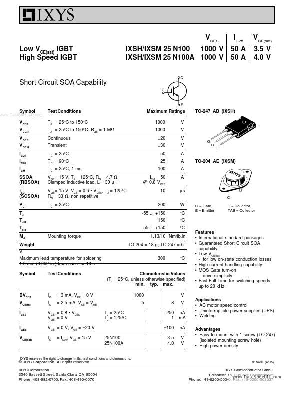
VCES Low VCE(sat) IGBT High Speed IGBT IXSH/IXSM 25 N100 1000 V IXSH/IXSM 25 N100A 1000 V
I C25 50 A 50 A
VCE(sat) 3.5 V 4.0 V
Short Circuit SOA Capability
..
Symbol V CES
Test Conditions TJ = 25°C to 150°C TJ = 25°C to 150° C; RGE = 1 MΩ Continuous Transient T C = 25°C T C = 90°C T C = 25°C, 1 ms V GE = 15 V, TJ = 125°C, RG = 4.7 Ω Clamped inductive load, L = 30 µ H V GE = 15 V, VCE = 0.6
- V CES, TJ = 125°C RG = 33 Ω, non repetitive T C = 25°C
Maximum Ratings 1000 1000 ±20 ±30 50 25 100 ICM = 50 @ 0.8 VCES 10 200 -55 ... +150 150 -55 ... +150 V V V V A A A A µs
TO-247 AD (IXSH)
V CGR V GES V GEM I C25 I C90 I CM SSOA (RBSOA) t SC (SCSOA) PC TJ TJM Tstg Md Weight g
TO-204 AE (IXSM)
W °C °C °C
G = Gate, E = Emitter,
C = Collector, TAB = Collector
Mounting torque
1.13/10 Nm/lb.in. TO-204 = 18 g, TO-247 = 6 300 °C
Maximum lead temperature for soldering 1.6 mm (0.062 in.) from case for 10 s Symbol Test Conditions
Characteristic Values (TJ = 25° C, unless otherwise specified) min. typ. max. 1000 5 TJ = 25°C TJ = 125°C 8 250 1 ±100 25N100 25N100A 3.5 4.0 V V µA m A n A V V
Features
International standard packages Guaranteed Short Circuit SOA capability Low VCE(sat)
- for low on-state conduction losses High current handling capability MOS Gate turn-on
- drive simplicity Fast Fall Time for switching speeds up to 20 k Hz q q q q q q
BVCES VGE(th) I CES I GES VCE(sat)
IC IC
= 3 m A, VGE = 0 V = 2.5 m A, VCE = VGE
V CE = 0.8
- VCES V GE = 0 V V CE = 0 V, VGE = ±20 V IC = IC90, VGE = 15 V
Applications AC motor speed control Uninterruptible power supplies (UPS) Welding q q q q q
Advantages Easy to mount with 1 screw (TO-247) (isolated mounting screw hole) High power...