Datasheet4U Logo Datasheet4U.com

IXGA7N60CD1 - IGBT

Download the IXGA7N60CD1 datasheet PDF. This datasheet also covers the IXGP7N60CD1 variant, as both devices belong to the same igbt family and are provided as variant models within a single manufacturer datasheet.

Key Features

  • G = Gate, E = Emitter, C = Collector, TAB = Collector.
  • International standard packages 0.45/4 Nm/lb. in. 0.55/5 Nm/lb. in. 4 2 g g JEDEC TO-263 surface mountable and JEDEC TO-220 AB.
  • High frequency IGBT.
  • High current handling capability.
  • HiPerFASTTM.

📥 Download Datasheet

Note: The manufacturer provides a single datasheet file (IXGP7N60CD1_IXYS.pdf) that lists specifications for multiple related part numbers.

Full PDF Text Transcription for IXGA7N60CD1 (Reference)

Note: Below is a high-fidelity text extraction (approx. 800 characters) for IXGA7N60CD1. For precise diagrams, and layout, please refer to the original PDF.

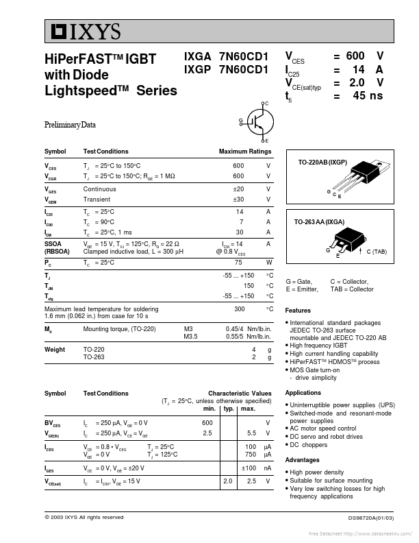
HiPerFASTTM IGBT with Diode IXGA 7N60CD1 IXGP 7N60CD1 LightspeedTM Series Preliminary Data Symbol VCES VCGR VGES VGEM IC25 IC90 ICM SSOA (RBSOA) PC TJ TJM Tstg Maximum le...

View more extracted text
ES VCGR VGES VGEM IC25 IC90 ICM SSOA (RBSOA) PC TJ TJM Tstg Maximum lead temperature for soldering 1.6 mm (0.062 in.) from case for 10 s Md Weight Mounting torque, (TO-220) TO-220 TO-263 M3 M3.5 Test Conditions TJ = 25°C to 150°C TJ = 25°C to 150°C; RGE = 1 MΩ Continuous Transient TC = 25°C TC = 90°C TC = 25°C, 1 ms VGE = 15 V, TVJ = 125°C, RG = 22 Ω Clamped inductive load, L = 300 µH TC = 25°C Maximum Ratings 600 600 ±20 ±30 14 7 30 ICM = 14 @ 0.8 VCES 75 -55 ... +150 150 -55 ... +150 300 V V V V A A A A VCES IC25 VCE(sat)typ tfi = 600 V = 14 A = 2.