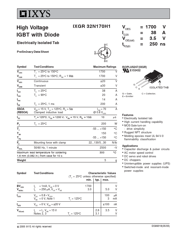
z Electrically Isolated tab z High current handling capability z MOS Gate turn-on
- drive simplicity z Rugged NPT structure z Molding epoxies meet UL 94 V-0
flammability classification.
Full PDF Text Transcription for IXGR32N170H1 (Reference)
Note: Below is a high-fidelity text extraction (approx. 800 characters) for
IXGR32N170H1. For precise diagrams, and layout, please refer to the original PDF.
High Voltage IGBT with Diode Electrically Isolated Tab Preliminary Data Sheet IXGR 32N170H1 IVCC2E5S VCE(sat) tfi(typ) = 1700 V = 38 A = 3.5 V = 250 ns Symbol Test Condit...
View more extracted text
VCE(sat) tfi(typ) = 1700 V = 38 A = 3.5 V = 250 ns Symbol Test Conditions Maximum Ratings VCES VCGR VGES VGEM IC25 IC90 IF90 ICM SSOA (RBSOA) tSC TJ = 25°C to 150°C TJ = 25°C to 150°C; RGE = 1 MΩ Continuous Transient 1700 1700 ±20 ±30 TC = 25°C TC = 90°C 38 20 14 TC = 25°C, 1 ms 200 VGE = 15 V, TVJ = 125°C, RG = 5Ω Clamped inductive load ICM = 70 @ 0.8 VCES TJ = 125°C, VCE = 1200 V; VGE = 15 V, RG = 10Ω 10 V V V V A A A A A μs PC TC = 25°C T J TJM Tstg FC Mounting force with clamp VISOL 50/60 Hz, 1 minute Maximum lead temperature for soldering 1.6 mm (0.062 in.) from case for 10 s Weight 200 -55 ... +150 150 -55 ... +150