Datasheet4U Logo Datasheet4U.com

IXGT15N120B2D1 - IGBT

Download the IXGT15N120B2D1 datasheet PDF. This datasheet also covers the IXGH15N120B2D1 variant, as both devices belong to the same igbt family and are provided as variant models within a single manufacturer datasheet.

Key Features

  • z International standard packages: JEDEC TO-247AD & TO-268 z IGBT and anti-parallel FRED in one package z MOS Gate turn-on - drive simplicity z Fast Recovery Expitaxial Diode (FRED) - soft recovery with low IRM Symbol Test Conditions (TJ = 25°C, unless otherwise specified) BV CES VGE(th) I C = 250 μA, V GE = 0 V IC = 250 μA, VCE = VGE ICES VCE = VCES V =0V GE I GES V CE = 0 V, V GE = ±20 V VCE(sat) IC = ICE90, VGE = 15 Characteristic Values Min. Typ. Max. 1200 2.5 V.

📥 Download Datasheet

Note: The manufacturer provides a single datasheet file (IXGH15N120B2D1-IXYS.pdf) that lists specifications for multiple related part numbers.

Full PDF Text Transcription (Reference)

The following content is an automatically extracted verbatim text from the original manufacturer datasheet and is provided for reference purposes only.

View original datasheet text
Advance Technical Information 
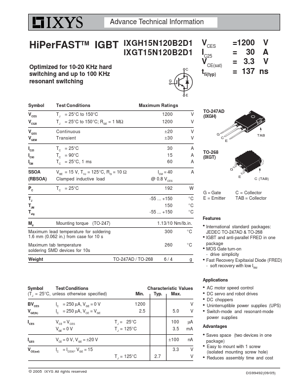
HiPerFASTTM IGBT IXGH15N120B2D1 IXGT15N120B2D1 Optimized for 10-20 KHz hard switching and up to 100 KHz resonant switching VCES IC25 VCE(sat) tfi(typ) =1200 V = 30 A = 3.3 V = 137 ns Symbol Test Conditions Maximum Ratings VCES VCGR VGES VGEM IC25 IC90 I CM SSOA (RBSOA) PC TJ TJM Tstg TJ = 25°C to 150°C TJ = 25°C to 150°C; RGE = 1 MΩ Continuous Transient TC = 25°C TC = 90°C T C = 25°C, 1 ms V GE = 15 V, T VJ = 125°C, R G = 10 Ω Clamped inductive load TC = 25°C 1200 V 1200 V ±20 V ±30 V 30 A 15 A 60 A I = 40 A CM @ 0.8 V CES 192 W -55 ... +150 °C 150 °C -55 ... +150 °C Md Mounting torque (TO-247) Maximum lead temperature for soldering 1.6 mm (0.062 in.