Datasheet4U Logo Datasheet4U.com

IXGT35N120B - IGBT

Download the IXGT35N120B datasheet PDF. This datasheet also covers the IXGH35N120B variant, as both devices belong to the same igbt family and are provided as variant models within a single manufacturer datasheet.

Key Features

  • International standard packages JEDEC TO-268 and JEDEC TO-247 AD.
  • Low switching losses, low V (sat).
  • MOS Gate turn-on - drive simplicity Symbol BVCES VGE(th) I CES IGES VCE(sat) Test Conditions IC = 1 mA, VGE = 0 V IC = 750 mA, VCE = VGE V =V CE CES VGE = 0 V VCE = 0 V, VGE = ±20 V IC = IC90, VGE = 15 V Characteristic Values (TJ = 25°C, unless otherwise specified) min. typ. max. T= J 25°C TJ = 125°C TJ = 125°C 1200 2.5 V 5V 250 mA 5 mA ±100 nA 3.3 V 2.7 V.

📥 Download Datasheet

Note: The manufacturer provides a single datasheet file (IXGH35N120B-IXYS.pdf) that lists specifications for multiple related part numbers.

Full PDF Text Transcription (Reference)

The following content is an automatically extracted verbatim text from the original manufacturer datasheet and is provided for reference purposes only.

View original datasheet text
Advance Technical Information HiPerFASTTM IGBT IXGH 35N120B IXGT 35N120B VCES = IC2 = VCE(sat) = =tfi(typ) 1200 V 70 A 3.3 V 160 ns Symbol Test Conditions Maximum Ratings VCES VCGR TJ = 25°C to 150°C TJ = 25°C to 150°C; RGE = 1 MW 1200 1200 V GES VGEM Continuous Transient ±20 ±30 IC25 TC = 25°C IC90 TC = 90°C ICM TC = 25°C, 1 ms 70 35 140 SSOA (RBSOA) V= GE 15 V, T VJ = 125°C, R G = 5 W Clamped inductive load I = 90 CM @ 0.8 VCES P C T C = 25°C 300 TJ -55 ... 
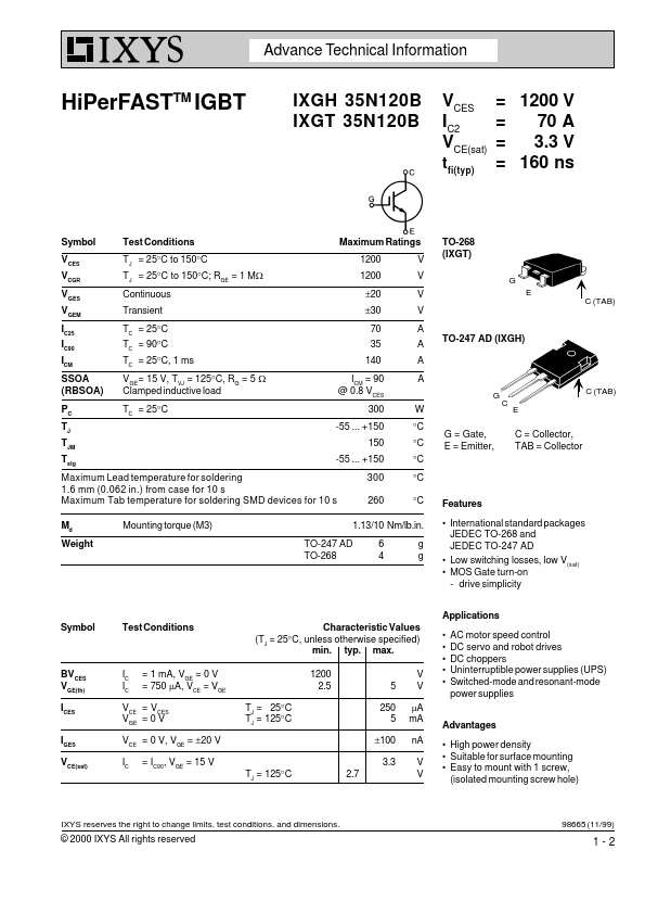
+150 T 150 JM Tstg -55 ... +150 Maximum Lead temperature for soldering 1.6 mm (0.062 in.) from case for 10 s Maximum Tab temperature for soldering SMD devices for 10 s 300 260 V V V V A A A A W °C °C °C °C °C M d Weight Mounting torque (M3) 1.13/10 Nm/lb.in.