Download the IXTP1R4N100P datasheet PDF.
This datasheet also covers the IXTY1R4N100P variant, as both devices belong to the same power mosfet family and are provided as variant models within a single manufacturer datasheet.
Key Features
z z z z z
S D (Tab)
TO-263 AA (IXTA)
G S D (Tab)
TO-220AB (IXTP)
G
DS
D (Tab)
1.6mm (0.062) from Case for 10s Plastic Body for 10s Mounting Force TO-252 TO-263 TO-220 (TO-263) Mounting Torque (TO-220)
300 260 10..65/2.2..14.6 1.13 / 10 0.35 2.50 3.00
G = Gate S = Source
D = Drain Tab = Drain
International Standard Packages Low RDS(on) and QG Avalanche Rated Low Package Inductance Fast Intrinsic Rectifier
Symbol Test Conditions (TJ = 25°C, Unless Otherwise Specified) BVDSS VGS(th) IG.
Full PDF Text Transcription for IXTP1R4N100P (Reference)
Note: Below is a high-fidelity text extraction (approx. 800 characters) for
IXTP1R4N100P. For precise diagrams, and layout, please refer to the original PDF.
PolarTM Power MOSFETs 
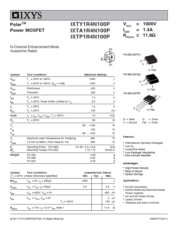
N-Channel Enhancement Mode Avalanche Rated IXTY1R4N100P IXTA1R4N100P IXTP1R4N100P VDSS ID25 RDS(on) = 1000V = 1.4A ≤ 11.8Ω TO-252 (IXTY) G Symbol VD...
View more extracted text
00P VDSS ID25 RDS(on) = 1000V = 1.4A ≤ 11.8Ω TO-252 (IXTY) G Symbol VDSS VDGR VGSS VGSM ID25 IDM IA EAS dv/dt PD TJ TJM Tstg TL TSOLD FC Md Weight Test Conditions TJ = 25°C to 150°C TJ = 25°C to 150°C, RGS = 1MΩ Continuous Transient TC = 25°C TC = 25°C, Pulse Width Limited by TJM TC = 25°C TC = 25°C IS ≤ IDM, VDD ≤ VDSS, TJ ≤ 150°C TC = 25°C Maximum Ratings 1000 1000 ±20 ±30 1.4 3.0 1.4 100 10 63 -55 ... +150 150 -55 ... +150 V V V V A A A mJ V/ns W °C °C °C °C °C N/lb. Nm/lb.in. g g g Features z z z z z S D (Tab) TO-263 AA (IXTA) G S D (Tab) TO-220AB (IXTP) G DS D (Tab) 1.6mm (0.