IDT74LVCH16374A
IDT74LVCH16374A is 3.3V CMOS 16-BIT EDGE-TRIGGERED D-TYPE FLIP-FLOP manufactured by Integrated Device Technology.
TION
DRIVE Features
: APPLICATIONS:
- High Output Drivers: ±24m A
- Reduced system switching noise
- 5V and 3.3V mixed voltage systems
- Data munication and telemunication systems
The LVCH16374A 16-bit edge-triggered D-type register is built using advanced dual metal CMOS technology. This high-speed, low-power register is ideal for use as a buffer register for data synchronization and storage. The Output Enable (OE) and clock (CLK) controls are organized to operate each device as two 8-bit registers or one 16-bit register with mon clock. Flow-through organization of signal pins simplifies layout. All inputs are designed with hysteresis for improved noise margin. All pins of the LVCH16374A can be driven from either 3.3V or 5V devices. This feature allows the use of this device as a translator in a mixed 3.3V/5V supply system. The LVCH16374A has been designed with a ±24m A output driver. This driver is capable of driving a moderate to heavy load while maintaining speed performance. The LVCH16374A has “bus-hold” which retains the inputs’ last state whenever the input goes to a high impedance. This prevents floating inputs and eliminates the need for pull-up/down resistors.
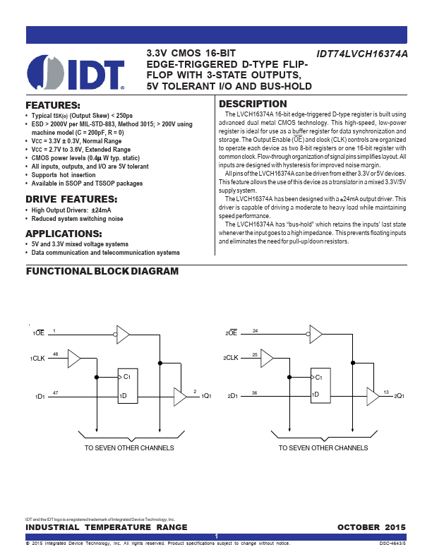
FUNCTIONAL BLOCK DIAGRAM
1OE
2OE
1CLK
2CLK
C1
1D1
C1
1D
1Q1
2D1
1D
2Q1
TO SEVEN OTHER CHANNELS
TO SEVEN OTHER CHANNELS
The IDT logo is a registered trademark of Integrated Device Technology, Inc.
INDUSTRIAL TEMPERATURE RANGE
© 1999 Integrated Device Technology, Inc.
MARCH 1999
DSC-4643/2
IDT74LVCH16374A 3.3V CMOS 16-BIT EDGE-TRIGGERED D-TYPE FLIP-FLOP
INDUSTRIAL TEMPERATURE...