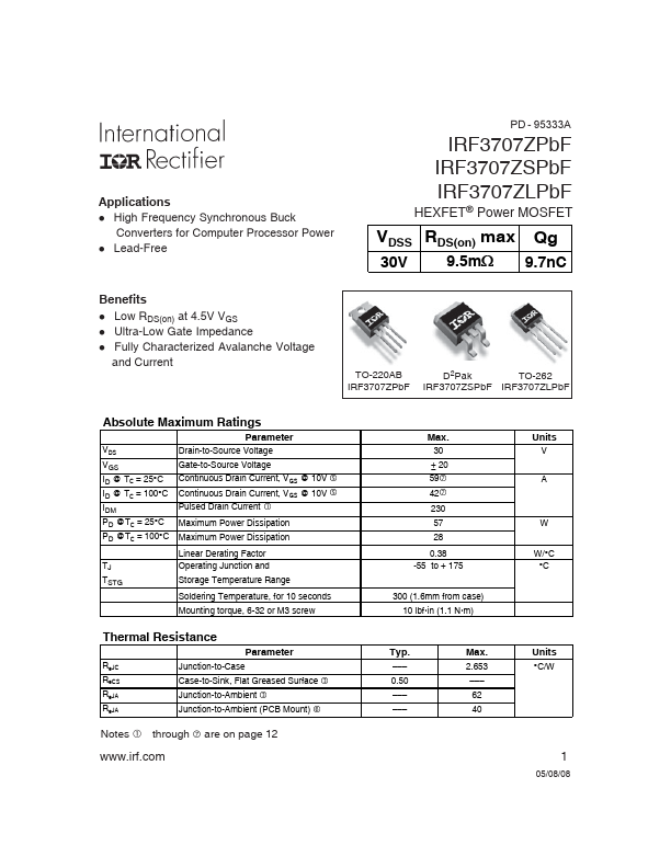
IRF3707ZPbF
Key Features
- 9.5 12.5 2.25
- 1.0 µA VDS = 24V, VGS = 0V
| Part Number | Manufacturer | Description |
|---|---|---|
| IRF3707Z | Inchange Semiconductor | N-Channel MOSFET |
| IRF3707ZS | Inchange Semiconductor | N-Channel MOSFET |
| IRF3704Z | Inchange Semiconductor | N-Channel MOSFET |
| IRF3703 | Inchange Semiconductor | N-Channel MOSFET |
| IRF3704ZCS | Inchange Semiconductor | N-Channel MOSFET |
| IRF3704ZS | Inchange Semiconductor | N-Channel MOSFET |
| IRF3708S | Inchange Semiconductor | N-Channel MOSFET |
| IRF3709Z | Inchange Semiconductor | N-Channel MOSFET |
| IRF3709ZCS | Inchange Semiconductor | N-Channel MOSFET |
| IRF3709ZS | Inchange Semiconductor | N-Channel MOSFET |