IRF7483MTRPbF
IRF7483MTRPbF is Power MOSFET manufactured by International Rectifier.
Application
- Brushed Motor drive applications
- BLDC Motor drive applications
- Battery powered circuits
- Half-bridge and full-bridge topologies
- Synchronous rectifier applications
- Resonant mode power supplies
- OR-ing and redundant power switches
- DC/DC and AC/DC converters
- DC/AC Inverters
Benefits
- Improved Gate, Avalanche and Dynamic dv/dt Ruggedness
- Fully Characterized Capacitance and Avalanche SOA
- Enhanced body diode dv/dt and di/dt Capability
- Lead-Free, RoHS pliant
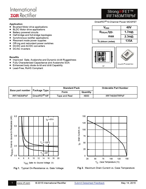
StrongIRFET™ IRF7483MTRPbF
DirectFET® N-Channel Power MOSFET
VDSS RDS(on) typ. max ID (Silicon Limited)
40V 1.7m 2.3m 135A
DirectFET® ISOMETRIC
Base part...