Datasheet4U Logo Datasheet4U.com

IRF7821PBF - Power MOSFET

Features

  • light load the MOSFET must still be turned on and off by the control IC so the gate drive losses become much more significant. Secondly, the output charge Qoss and reverse recovery charge Qrr both generate losses that are transfered to Q1 and increase the dissipation in that device. Thirdly, gate charge will impact the MOSFETs’ susceptibility to Cdv/dt turn on. The drain of Q2 is connected to the switching node of the converter and therefore sees transitions between ground and Vin. As Q1 turns o.

📥 Download Datasheet

Datasheet preview – IRF7821PBF
Other Datasheets by International Rectifier

Full PDF Text Transcription

Click to expand full text
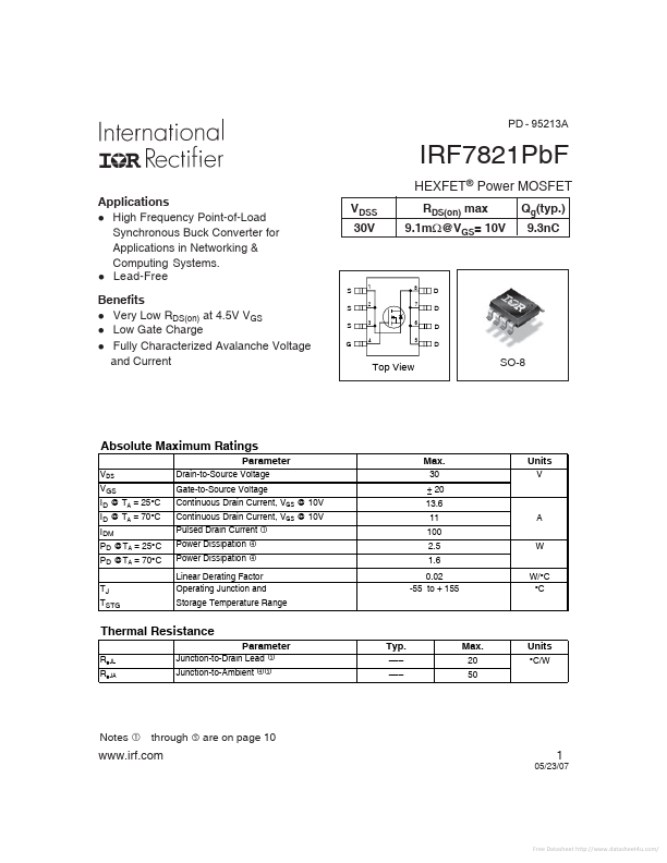
PD - 95213A IRF7821PbF HEXFET® Power MOSFET Applications l High Frequency Point-of-Load Synchronous Buck Converter for Applications in Networking & Computing Systems. l Lead-Free Benefits l Very Low RDS(on) at 4.5V VGS l Low Gate Charge l Fully Characterized Avalanche Voltage and Current VDSS 30V RDS(on) max 9.1mW@VGS= 10V Qg(typ.) 9.3nC S S S G 1 2 3 4 8 7 A A D D D D 6 5 Top View SO-8 Absolute Maximum Ratings Parameter VDS VGS ID @ TA = 25°C ID @ TA = 70°C IDM PD @TA = 25°C PD @TA = 70°C TJ TSTG Drain-to-Source Voltage Gate-to-Source Voltage Continuous Drain Current, VGS @ 10V Continuous Drain Current, VGS @ 10V Pulsed Drain Current Power Dissipation Power Dissipation Max. 30 ± 20 13.6 11 100 2.5 1.6 0.
Published: |