IRF7831PBF Overview
Key Specifications
Package: SOIC
Mount Type: Surface Mount
Pins: 8
Height: 1.4986 mm
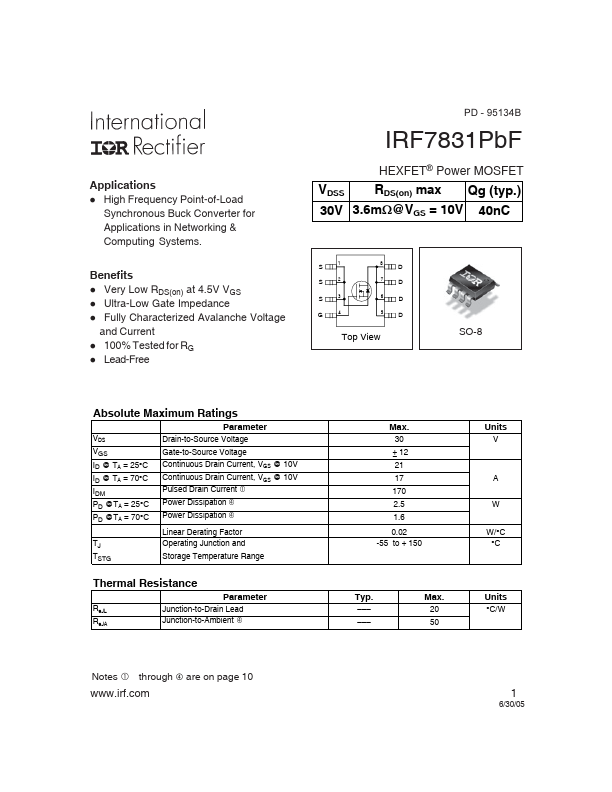
| Part | IRF7831PBF |
|---|---|
| Description | Power MOSFET |
| Category | MOSFET |
| Manufacturer | International Rectifier |
| Size | 261.12 KB |
Package: SOIC
Mount Type: Surface Mount
Pins: 8
Height: 1.4986 mm
| Seller | Inventory | Price Breaks | Buy |
|---|---|---|---|
| RS (Formerly Allied Electronics) | 0 | 3800+ : 1.86 USD 7600+ : 1.823 USD 19000+ : 1.767 USD 38000+ : 1.693 USD |
View Offer |
| Win Source | 3365 | 55+ : 1.1435 USD 125+ : 0.9379 USD 195+ : 0.909 USD 265+ : 0.8801 USD |
View Offer |
| Part Number | Manufacturer | Description |
|---|---|---|
| IRF7832 | Freescale Semiconductor | N-Channel 30-V (D-S) MOSFET |