IRFS4610PBF
IRFS4610PBF is HEXFET Power MOSFET manufactured by International Rectifier.
- Part of the IRFB4610PBF comparator family.
- Part of the IRFB4610PBF comparator family.
- 95936B
IRFB4610Pb F IRFS4610Pb F IRFSL4610Pb F
Applications l High Efficiency Synchronous Rectification in SMPS l Uninterruptible Power Supply l High Speed Power Switching l Hard Switched and High Frequency Circuits l Lead-Free Benefits l Improved Gate, Avalanche and Dynamic d V/dt Ruggedness l Fully Characterized Capacitance and Avalanche SOA l Enhanced body diode d V/dt and d I/dt Capability
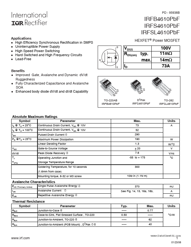
HEXFET® Power MOSFET
VDSS RDS(on) typ. max. ID
100V 11m: 14m: 73A
TO-220AB IRFB4610Pb F
S GD
D2Pak IRFS4610Pb F
TO-262 IRFSL4610Pb F
Absolute Maximum Ratings
Symbol
ID @ TC = 25°C ID @ TC = 100°C IDM PD @TC = 25°C VGS d V/dt TJ TSTG
Parameter
Continuous Drain Current, VGS @ 10V Continuous Drain Current, VGS @ 10V Pulsed Drain Current
Max.
73 52 290 190 1.3 ± 20 7.6 -55 to + 175 300 10lb in (1.1N m)
Units
A f
Maximum Power Dissipation Linear Derating Factor Gate-to-Source Voltage Peak Diode Recovery Operating Junction and Storage Temperature Range Soldering Temperature, for 10 seconds (1.6mm from case) Mounting torque, 6-32 or M3 screw
W W/°C V V/ns °C e x x
Avalanche Characteristics
EAS (Thermally limited) IAR EAR Single Pulse Avalanche Energy Avalanche Current
à d
370 See Fig. 14, 15, 16a, 16b, m J A m J
Repetitive Avalanche Energy f
Thermal Resistance
Symbol
RθJC RθCS RθJA RθJA Junction-to-Case j
Parameter
Typ.
- -
- 0.50
- -
- -
- -...