IRGSL14C40LPBF
IRGSL14C40LPBF is IGBT manufactured by International Rectifier.
- Part of the IRGB14C40LPBF comparator family.
- Part of the IRGB14C40LPBF comparator family.
Features
Most Rugged in Industry Logic-Level Gate Drive > 6KV ESD Gate Protection Low Saturation Voltage High Self-clamped Inductive Switching Energy Lead-Free Description
The advanced IGBT process family includes a MOS gated, N-channel logic level device which is intended for coil-on-plug automotive ignition applications and small-engine ignition circuits. Unique features include on-chip active voltage clamps between the Gate-Emitter and Gate-Collector which provide over voltage protection capability in ignition circuits.
..
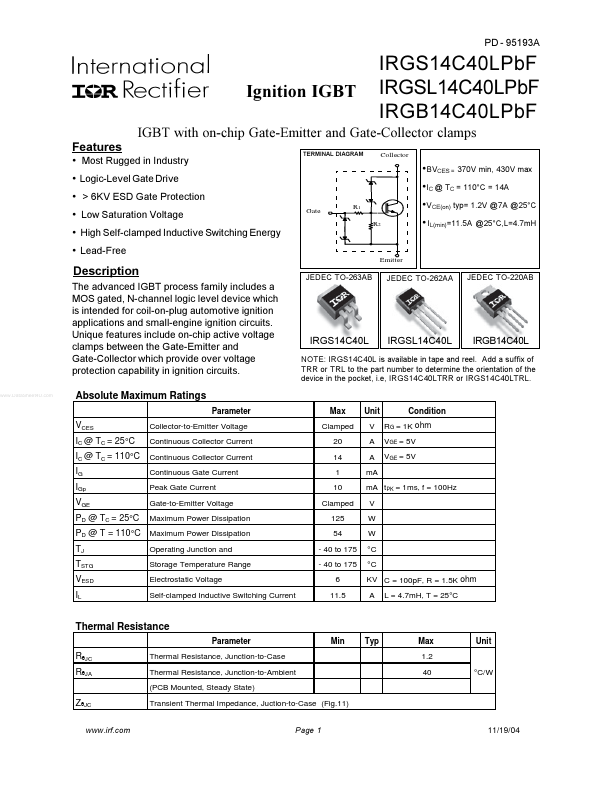
IGBT with on-chip Gate-Emitter and Gate-Collector clamps
TERMINAL DIAGRAM
Collector
IRGS14C40LPb F IRGSL14C40LPb F IRGB14C40LPb F
BVCES = 370V min, 430V max IC @ TC = 110°C = 14A VCE(on) typ= 1.2V @7A @25°C IL(min)=11.5A @25°C,L=4.7m H
Gate
R1 R2
Emitter
JEDEC TO-263AB
JEDEC TO-262AA
JEDEC TO-220AB
IRGS14C40L
IRGSL14C40L
IRGB14C40L
NOTE: IRGS14C40L is available in tape and reel. Add a suffix of TRR or TRL to the part number to determine the orientation of the device in the pocket, i.e, IRGS14C40LTRR or IRGS14C40LTRL.
Absolute Maximum Ratings
Parameter Max Clamped 20 14 1 10 Clamped 125 54
- 40 to 175
- 40 to 175 6 11.5 Unit V A A m A m A t PK = 1ms, f = 100Hz V W W °C °C KV C = 100p F, R = 1.5K ohm A L = 4.7m H, T = 25°C Condition RG = 1K ohm VGE = 5V VGE = 5V
VCES IC @ TC = 25°C IC @ TC = 110°C IG IGp VGE PD @ TC = 25°C TJ TSTG VESD IL
Collector-to-Emitter Voltage Continuous Collector Current Continuous Collector Current Continuous Gate Current Peak Gate Current Gate-to-Emitter Voltage Maximum Power Dissipation
PD @ T = 110°C Maximum Power Dissipation
Operating Junction and Storage Temperature Range Electrostatic Voltage Self-clamped Inductive Switching Current
Thermal Resistance
Parameter Min Typ Max 1.2 40 °C/W Unit
RθJC RθJA ZθJC
.irf.
Thermal Resistance, Junction-to-Case Thermal Resistance, Junction-to-Ambient (PCB Mounted, Steady State) Transient Thermal Impedance, Juction-to-Case (Fig.11)
Page 1
11/19/04
Igni...