Datasheet4U Logo Datasheet4U.com

ISL95711 - 128 Taps I2C Serial Interface

General Description

PIN NUMBER 1 2 3 4 5 6 7 8 9 10 SYMBOL SDA VGND A1 A0 RH RW RL VCC SCL active low outputs.

Negative supply voltage for the potentiometer wiper control.

Ground.

Key Features

  • Non-Volatile Solid-State Potentiometer.
  • I2C Serial Interface with Hardwire Slave Address Allows Up to Four Devices.
  • DCP Terminal Voltage, from V- to VCC.
  • 128 Wiper Tap Points - Wiper position can be stored in nonvolatile memory and recalled on power-up.
  • 127 Resistive Elements - Typical tempco ±50ppm/°C - Ratiometric Tempco ±4ppm/°C - End to end resistance range ±20%.
  • Low Power CMOS - Standby current, 1µA - Active current, 200µA max - VCC = 3.

📥 Download Datasheet

Full PDF Text Transcription (Reference)

The following content is an automatically extracted verbatim text from the original manufacturer datasheet and is provided for reference purposes only.

View original datasheet text
® ISL95711 Digitally Controlled Potentiometer (XDCP™) Data Sheet August 15, 2005 FN8241.2 Terminal Voltage ±3V or ±5V, 128 Taps I2C Serial Interface 
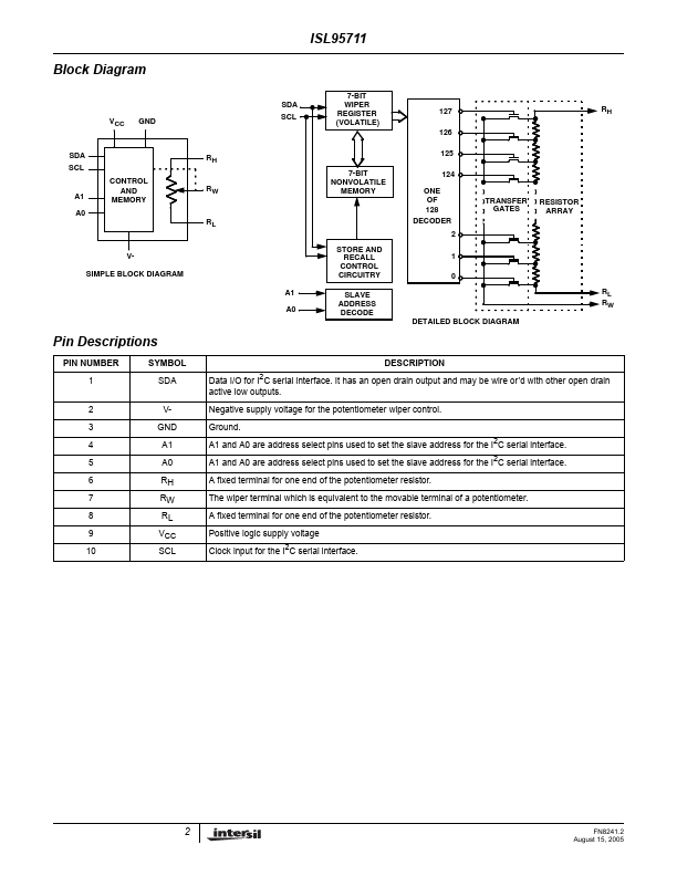
The Intersil ISL95711 is a digitally controlled potentiometer (XDCP). The device consists of a resistor array, wiper switches, a control section, and nonvolatile memory. The wiper position is controlled by a I2C interface. The potentiometer is implemented by a resistor array composed of 127 resistive elements and a wiper switching network. The wiper terminal can be connected to either end of the resistor array or at any one of the Tap Positions in between, providing 128 steps of resolution between RL and RH. The “position” of the wiper is determined by the value assigned to the volatile Wiper Register (WR).