Datasheet4U Logo Datasheet4U.com

ISL90843 - Quad Digital Controlled Potentiometers

General Description

MSOP PIN 1 2 3 4 5 6 7 8 9 10 SYMBOL RW3 SCL SDA GND RW2 RW1 A0 A1 VCC RW0 “Wiper” terminal of DCP3 I2C interface clock Serial data I/O for the I2C interface Device ground pin “Wiper” terminal of DCP2 “Wiper” terminal of DCP1 Device address for the I2C interface Device address for the I2C interface

Key Features

  • Four potentiometers in one package.
  • 256 resistor taps.
  • 0.4% resolution.
  • I2C serial interface - Two address pins allow up to four devices/bus.
  • Wiper resistance: 70Ω typical @ 3.3V.
  • Standby current.

📥 Download Datasheet

Full PDF Text Transcription (Reference)

The following content is an automatically extracted verbatim text from the original manufacturer datasheet and is provided for reference purposes only.

View original datasheet text
® ISL90843 
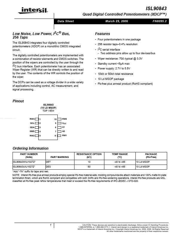
Quad Digital Controlled Potentiometers (XDCP™) Data Sheet March 29, 2006 FN8095.2 Low Noise, Low Power, I2C® Bus, 256 Taps The ISL90843 integrates four digitally controlled potentiometers (XDCP) on a monolithic CMOS integrated circuit. The digitally controlled potentiometers are implemented with a combination of resistor elements and CMOS switches. The position of the wipers are controlled by the user through the I2C bus interface. Each potentiometer has an associated Wiper Register (WR) that can be directly written to and read by the user. The contents of the WR controls the position of the wiper. The DCPs can be used as a voltage divider in a wide variety of applications including control, AC measurement, and signal processing.