KK494
KK494 is PWM Control Circuit manufactured by Kodenshi AUK Group.
..
TECHNICAL DATA
PWM Control Circuit
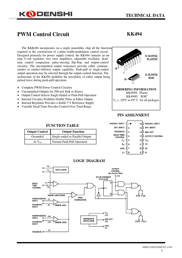
The KKK494 incorporates on a single monolithic chip all the functions required in the construction of a pulse-width-modulation control circuit. Designed primarily for power supply control, the KK494 contains an onchip 5-volt regulator, two error amplifiers, adjustable oscillator, deadtime control parator, pulse-steering flip-flop, and output-control circuitry. The unmitted output transistors provide either monemitter or emitter-follower output capability. Push-pull or single-ended output operation may be selected through the output-control function. The architecture of the KK494 prohibits the possibility of either output being pulsed twice during push-pull operation.
- -
- -
- - plete PWM Power Control Circuitry Unmitted Outputs for 200 m A Sink or Source Output Control Selects Single-Ended or Push-Pull Operation Internal Circuitry Prohibits Double Pulse at Either Output Internal Regulator Provides a Stable 5 V Reference Supply Variable Dead-Time Provides Control Over Total Range
ORDERING INFORMATION KK494N Plastic KK494D SOIC TA = -20°C to 85° C for all packages
PIN ASSIGNMENT FUNCTION TABLE
Output Control Grounded At Vref Output Function Single-ended or Parallel Output Normal Push-Pull Operation
LOGIC DIAGRAM
..
MAXIMUM RATINGS
Symbol VCC VI VO Tstg Supply Voltage Amplifier Input Voltage Collector Output Voltage Collector Output Current Storage Temperature Parameter Value 41 VCC +0.3 41 250 -65 to +150 Unit V V V m A °C
REMENDED OPERATING CONDITIONS
Symbol VCC VI VO Supply Voltage Amplifier Input Voltage Collector Output Voltage Collector Output Current (Each Transistor) Current Into Feed back Terminal CT RT TA Timing Capacitor Timing Resistor Oscillator Frequency Operating Free-Air Temperature 0.47 1.8 1 -20 Parameter Min 7 -0.3 Max 40 VCC
- 2 40 200 0.3 10.000 500 300 +85 Unit V V V m A m A n F KΩ KHz °C
..
ELECTRICAL...