KKA3010
KKA3010 is INFRARED REMOTE CONTROL TRANSMITTER RC-5 manufactured by Kodenshi AUK Group.
DESCRIPTION
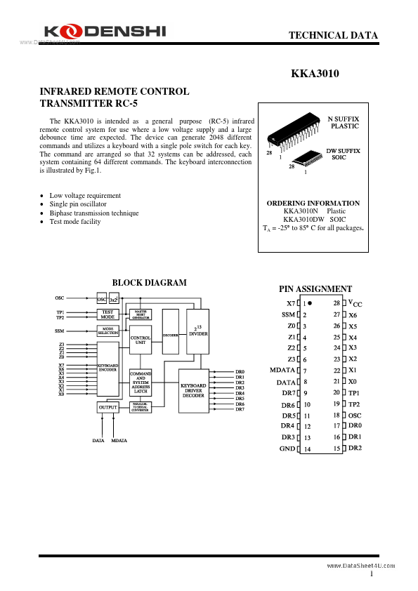
PIN No 1 2 3-6 7 DESIGNATION X7 (IPU) SSM (I) Z0-Z3 (IPU) MDATA (OP3) DESCRIPTION sense input from key matrix system mode selection input sense inputs from key matrix generated output data modulated with 1/2 the oscillator frequency at a 25% duty factor generated output information scan drivers ground (0V) scan drivers oscillator input test point 2 test point 1 sense inputs from key matrix voltage supply
8 DATA (OP3) 9-13 DR7-DR3 (ODN) 14 GND 15-17 DR2-DR0 (ODN) 18 OSC (I) 19 TP2 (I) 20 TP1 (I) 21-27 X0-X6 (IPU) 28 Vcc (I) (I) = input (IPU) = input with p-channel pull-up transistor (ODN) = output with open drain n-channel transistor (OP3) = output 3-state
FUNCTIONAL DESCRIPTION
Keyboard operation Every connection of one X-input and one DR-output will be recognized as a legal key operation and will cause the device to generate the corresponding code. The same applies to every connection of one Z-input to one DR-output with the proviso that SSM must be LOW. When SSM is HIGH a wired connection must exist between a Z-input and DRoutput. If no connection is present the system number will not be generated. Activating two or more X-inputs, Z-inputs or Z-inputs and X-inputs at the same time is an illegal action and inhibits further activity (oscillator will not start). When one X- or Z-input is connected to more than one DR-output, the last scan signal will be considered as legal. The maximum value of the contact series resistance of the switched keyboard is 7KΩ. Inputs In the quiescent state the mand inputs X0 to X7 are held HIGH by an internal pull-up transistor. When the system mode selection (SSM) input is LOW and the system is quiescent, the system inputs Z0 to Z3 are also held HIGH by an internal pull-up transistor. When SSM is HIGH the pull-up transistor for the Z-inputs is switched off, in order to prevent current flow, and a wired connection in the Z-DR matrix provides the system number. Outputs The output signal DATA transmits the generated...