FEATURES
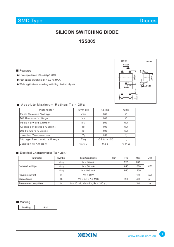
Low capacitance: Ct = 4.0 pF MAX. High speed switching: trr = 3.0 ns MAX. Wide applications including switching, limitter, clipper. A b s o lu te M a x im u m R a tin g s T a = 2 5 P aram eter P eak R everse V oltage D C R everse V oltage P eak Forw ard C urrent A verage R ectified C urrent D C Forw ard C urrent Junction T em perature S torage Tem perature R ange Junction to A m bient Sym bol VRM VR IF M IO IF Tj T stg R th ( j-a ) R ating 100 100 300 100 100 150 -55 to +150 0 .8 5 U nit V V mA mA mA mW ELECTRICAL CHARACTERISTICS
Ta = 25 Parameter Forward voltage Reverse current Capacitance Reverse recovery time Symbol Test Conditions Min VF(1) IF = 10 mA VF(2) IF = 50 mA VF(3) IF = 100 mA IR VR = 50 V Ct VR = 0, f = 1.0 MHz trr IF = 10 mA, VR = 6 V, RL = 100 ? , Typ Max Unit 720 850 850 1000 mV 950 1200 1.0 A 2.0 4.0 pF 3.0 ns Marking Marking A14 1