FEATURES
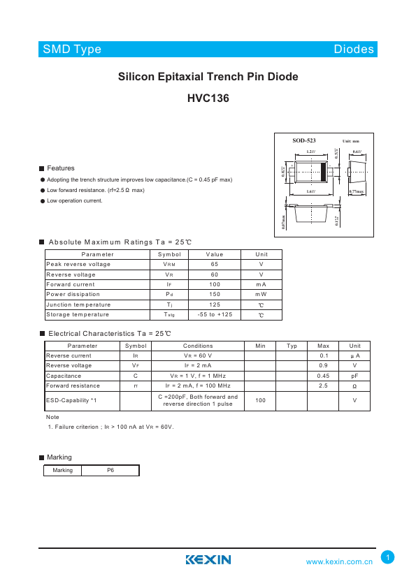
Adopting the trench structure improves low capacitance.(C = 0.45 pF max) Low forward resistance. (rf=2.5 max) Low operation current. +0.05 0.8 -0.05 SOD-523 1.2+0.1 -0.1 + +0.05 0.3 -0.05 Unit: mm 0.6+0.1 -0.1 - 1.6+0.1 -0.1 0.77max +0.05 0.1 -0.02 0.07max A bsolute M axim um R atings T a = 25 Param eter P eak reverse voltage R everse voltage Forward current P ower dissipation Junction tem perature Storage tem perature Sym bol VRM VR IF Pd Tj T stg V alue 65 60 100 150 125 -55 to +125 U nit V V mA mW ELECTRICAL CHARACTERISTICS
Ta = 25 P aram eter Reverse current Reverse voltage Capacitance Forward resistance ESD-Capability *1 Sym bol Conditions Min Typ Max Unit IR VR = 60 V 0.1 A VF IF = 2 mA 0.9 V C VR = 1 V, f = 1 MHz 0.45 pF rf IF = 2 mA, f = 100 MHz 2.5 C =200pF, Both forward and reverse direction 1 pulse 100 V Note 1. Failure criterion ; IR > 100 nA at VR = 60V. Marking Marking P6 1