FEATURES
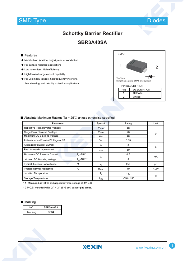
ƽ Metal silicon junction, majority carrier conduction ƽ For surface mounted applications ƽ Low power loss, high efficiency ƽ High forward surge current capability ƽ For use in low voltage, high frequency inverters, free wheeling, and polarity protection applications SMAF 1 2 Top View Simplified outline SMAF and symbol PIN DESCRIPTION
PIN DESCRIPTION
1 Cathode 2 Anode Ƶ ABSOLUTE MAXIMUM RATINGS
Ta = 25ć unless otherwise specified Parameter Repetitive Peak Reverse Voltage Surge Peak Reverse Voltage Maximum DC Blocking Voltage Instantaneous Forward Voltage at 3A Averaged Forward Current Peak forward surge current Maximum DC Reverse Current at rated DC blocking voltage Typical Junction Capacitance TA=25ć TA=100ć *1 Typical thermal resistance *2 Junction Temperature Storage Temperature * 1 Measured at 1MHz and applied reverse voltage of 4V D.C * 2 P.C.B. mounted with 2ą× 2ą(5×5 cm) copper pad areas. Symbol VRRM VRSM VDC VF IO IFSM IR Cj RthJA Tj Tstg Rating 40 28 40 0.55 3 80 0.5 5 250 70 150 -55 to 150 Ƶ Marking NO.