LS7082N
LS7082N is QUADRATURE CLOCK CONVERTER manufactured by LSI.
FEATURES
:
- x1, x2 and x4 mode selection
- Up to 16MHz output clock frequency
- INDEX input and output
- UP/DOWN indicator output
- Programmable output clock pulse width
- On-chip filtering of inputs for optical or magnetic encoder applications.
- TTL and CMOS patible I/Os
- +4.5V to +10V operation (VDD
- VSS)
- LS7082N (DIP); LS7082N-S (SOIC )
- See Figure 1
DESCRIPTION
: The LS7082N is a CMOS quadrature clock converter. Quadrature clocks derived from optical or magnetic encoders, when applied to the A and B Inputs of the LS7082, are converted to strings of Up Clocks and Down Clocks. Pulses derived from the Index Track of an encoder, when applied to the INDX input, produce absolute position reference pulses which are synchronized to the Up Clocks and Down Clocks. These outputs can be interfaced directly with standard Up/Down counters for direction and position sensing of the encoder.
INPUT/OUTPUT DESCRIPTION
: VDD (Pin 1) Supply Voltage positive terminal.
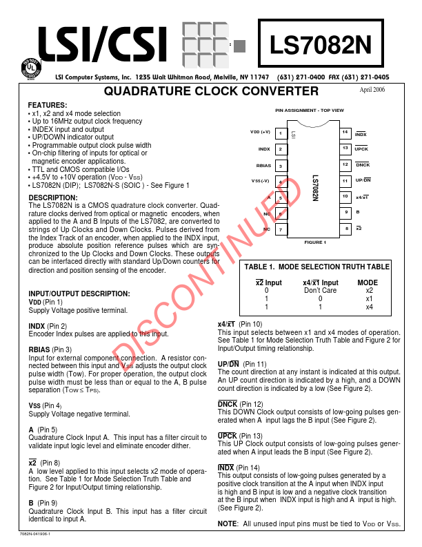
PIN ASSIGNMENT
- TOP VIEW
V DD (+V) 1
INDX 2
RBIAS 3
V SS (-V)
A5
NC 6 NC 7
FIGURE 1
14 INDX 13 UPCK 12 DNCK 11 UP/DN 10 x4/x1
9B 8 x2
TABLE 1. MODE SELECTION TRUTH TABLE x2 Input 0 1 1 x4/x1 Input Don’t Care
0 1
MODE x2 x1 x4
INDX (Pin 2) Encoder Index pulses are applied to this input.
RBIAS (Pin 3) Input for external ponent connection. A resistor connected between this input and VSS adjusts the output clock pulse width (Tow). For proper operation, the output clock pulse width must be less than or equal to the A, B pulse separation (TOW ≤ TPS). x4/x1 (Pin 10) This input selects between x1 and x4 modes of operation. See Table 1 for Mode Selection Truth Table and Figure 2 for Input/Output timing relationship.
UP/DN (Pin 11) The count direction at any instant is indicated at this output. An UP count direction is indicated by a high, and a DOWN count direction is indicated by a low (See Figure 2).
VSS (Pin 4) Supply Voltage negative terminal.
A (Pin 5) Quadrature Clock Input A. This...