MP1423
MP1423 is RTD Input Limit Alarm manufactured by M-System.
- Part of the MP1423_M comparator family.
- Part of the MP1423_M comparator family.
INSTRUCTION MANUAL
RTD INPUT LIMIT ALARM
Thank you for choosing M-System. Before use, check specifications on the unit label. If you have any problems or questions with the product, please contact M-System’s Sales Office or representatives. model MP1400 through MP1423
Adjustments
- Setpoint The MP1400 Series has five styles of setpoint adjustment: MP14X0 Top-accessed, 3-turn screw(s) MP14X2 Remote dial connection(s), 1k to 100k ohms MP14X3 DC-programmable, 0 to 1V The setpoint is adjustable over the entire input span. A) Set deadband at its minimum (fully counterclockwise) before adjusting the setpoint. B) With the specified trip Resistance/RTD input applied, adjust setpoint until the relay trips. For Hi trip calibration, start with the setpoint above the desired trip. For Lo trip calibration start below the desired trip.
- Deadband The deadband is independently adjustable for both setpoints in dual alarms. A) Set deadband at its minimum (fully counterclockwise). Set setpoint to desired trip. B) Adjust Resistance/RTD input until relay trips. C) Re-adjust deadband to 100% (fully clockwise). D) Set Resistance/RTD input to desired deadband position. E) Slowly adjust deadband until relay untrips.
- Transmitter Output (Option T) A) With the specified minimum input applied, adjust Zero for 0.00V at the transmitter output. B) With the specified maximum input applied, adjust Span for 1.00V. Repeat A) to B) for best accuracy.
General Description
The M-PAC Model MP1400 through MP1423 accept 2- or 3-wire RTD inputs and provide relay contact closure(s) at a preset input level. The MP1400 Series reflects three styles of output selection: MP1400
- MP1403 Single (Hi) trip, non-latching (DPDT, 3A) MP1410
- MP1413 Single (Hi) trip, latching (DPDT, 3A) MP1420
- MP1423 Dual (Hi/Lo) trip, non-latching (SPDT, 3A)
- Upscale burnout protection as standard
- Failsafe operation available
- Deadband adjustable from 1 to 100% ..
- Indicator LED provided
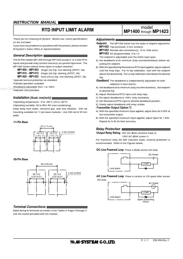
Installation [Scale:...