Datasheet4U Logo Datasheet4U.com

MAP7102 - Dual Output LCD Bias IC

Description

The MAP7102 is designed to support positive / negative driven TFT-LCD panels.

The two output rails are usually connected to the Source Driver IC.

The device uses a single inductor scheme in order to provide the user the smallest solution size possible as well as high efficiency.

Features

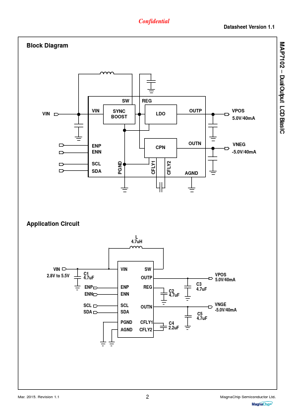
  • SIMO(Single-Inductor Multiple output) regulator Technology.
  • 86% Efficiency for 20mA Load current Between +5.0V and -5.0V.
  • 2.8V to 5.5V Input Voltage Range.
  • Under-Voltage Lockout Rising/Falling.
  • Programmable Output Voltages.
  • Positive Output Voltage Range : 4.0V to 5.7V (.

📥 Download Datasheet

Datasheet preview – MAP7102

Datasheet Details

Part number MAP7102
Manufacturer MagnaChip
File Size 1.00 MB
Description Dual Output LCD Bias IC
Datasheet download datasheet MAP7102 Datasheet
Additional preview pages of the MAP7102 datasheet.
Other Datasheets by MagnaChip

Full PDF Text Transcription

Click to expand full text
MAP7102 – DualOutput LCDBiasIC Confidential Datasheet Version 1.1 MAP7102 Dual Output LCD Bias IC General Description The MAP7102 is designed to support positive / negative driven TFT-LCD panels. The two output rails are usually connected to the Source Driver IC. The device uses a single inductor scheme in order to provide the user the smallest solution size possible as well as high efficiency. With its input voltage range of 2.8V to 5.5V, it is optimized for products powered by single-cell batteries and output currents up to 50mA. The device is delivered in a WLCSP package of 15 balls.
Published: |