FEATURES
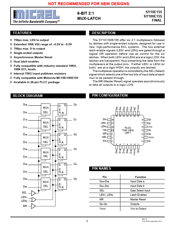
750ps max. LEN to output Extended 100E VEE range of –4.2V to –5.5V 700ps max. D to output Single-ended outputs Asynchronous Master Reset Dual latch-enables Fully compatible with industry standard 10KH, 100K ECL levels Internal 75KΩ input pulldown resistors Fully compatible with Motorola MC10E/100E155 Available in 28-pin PLCC package DESCRIPTION
If either LEN1 or LEN2 (or both) are at a logic HIGH, the outputs are latched. The multiplexer operation is controlled by the SEL (Select) signal which selects one of the two bits of input data at each mux to be passed through. The MR (Master Reset) signal operates asynchronously to take all outputs to a logic LOW. BLOCK DIAGRAM D0a D0b D1a D1b D2a D2b D3a D3b D4a D4b D5a D5b SEL LEN1 LEN2 MR MUX SEL MUX SEL MUX SEL MUX SEL MUX SEL MUX SEL DQ E NR DQ E NR DQ E NR DQ E NR DQ E NR DQ E NR Q0 Q1 Q2 Q3 Q4 Q5 PIN CONFIGURATION D5a D4b D4a D3b D3a NC VCCO D5b LEN1 LEN2 VEE MR SEL D0b 25 24 23 22 21 20 19 26 18 27 17 28 PLCC 16 1 TOP VIEW 15 2... Micrel