M54566P
M54566P is 7-UNIT 400mA DARLINGTON TRANSISTOR ARRAY manufactured by Mitsubishi Electric.
- Part of the M54566FP comparator family.
- Part of the M54566FP comparator family.
DESCRIPTION
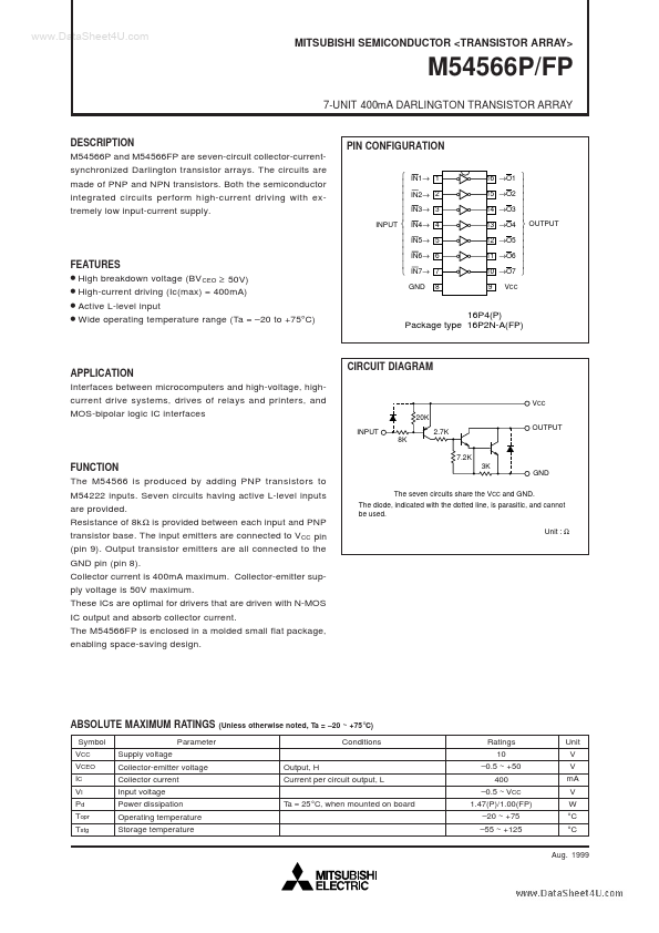
M54566P and M54566FP are seven-circuit collector-currentsynchronized Darlington transistor arrays. The circuits are made of PNP and NPN transistors. Both the semiconductor integrated circuits perform high-current driving with extremely low input-current supply. PIN CONFIGURATION
INPUT
IN1→ 1 IN2→ 2 IN3→ 3 IN4→ 4 IN5→ 5 IN6→ 6 IN7→ 7 GND 8 16 →O1 15 →O2 14 →O3 13 →O4 OUTPUT 12 →O5 11 →O6 10 →O7 9 VCC
FEATURES
High breakdown voltage (BV CEO ≥ 50V) High-current driving (Ic(max) = 400m A) Active L-level input Wide operating temperature range (Ta =
- 20 to +75°C)
16P4(P) Package type 16P2N-A(FP)
APPLICATION Interfaces between microputers and high-voltage, highcurrent drive systems, drives of relays and printers, and MOS-bipolar logic IC interfaces
CIRCUIT DIAGRAM
VCC 20K INPUT 8K 7.2K 2.7K OUTPUT
FUNCTION The M54566 is produced by adding PNP transistors to M54222 inputs. Seven circuits having active L-level inputs are provided. Resistance of 8k Ω is provided between each input and PNP transistor base. The input emitters are connected to VCC pin (pin 9). Output transistor emitters are all connected to the GND pin (pin 8). Collector current is 400m A maximum. Collector-emitter supply voltage is 50V maximum. These ICs are optimal for drivers that are driven with N-MOS IC output and absorb collector current. The M54566FP is enclosed in a molded small flat package, enabling space-saving design.
3K GND The seven circuits share the VCC and GND. The diode, indicated with the dotted line, is parasitic, and cannot be used. Unit : Ω
ABSOLUTE MAXIMUM RATINGS
Symbol VCC VCEO IC VI Pd Topr Tstg Parameter Supply voltage Collector-emitter voltage Collector current Input voltage Power dissipation Operating temperature Storage temperature
(Unless otherwise noted, Ta =
- 20 ~ +75 °C)
Conditions Output, H Current per circuit output, L Ta = 25 °C, when mounted on board
Ratings 10
- 0.5 ~ +50 400
- 0.5 ~ VCC...