MG400Q2YS60A
MG400Q2YS60A is High Power Switching Applications Motor Control Applications manufactured by Mitsubishi Electric.
..
MITSUBISHI IGBT Module
High Power Switching Applications Motor Control Applications
- -
- - Integrates a plete half bridge power circuit and fault-signal output circuit in one package. (short circuit and over temperature) The electrodes are isolated from case. Low thermal resistance. VCE (sat) = 2.4 V (typ.)
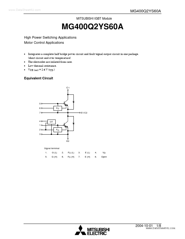
Equivalent Circuit
C1
5 6 7 FO E1/C2
4 1 2 3
E2 Signal terminal 1. 5. G (L) G (H) 2. 6. FO (L) FO (H) 3. 7. E (L) E (H) 4. 8. VD Open
2004-10-01
1/8
Package Dimensions
1. 5.
G (L) G (H)
2. 6.
FO (L) FO (H)
3. 7.
E (L) E (H)
4. 8.
VD Open
Signal Terminal Layout
1. 7 5 8 2.54 25.4 ± 0.6 6 2. 3. 4. 5. 6. 7. 2.54 8.
G (L) FO (L) E (L) VD G (H) FO (H) E (H) Open
3 1
4 2
Weight: 375 g
2004-10-01
2/8
Maximum Ratings (Ta = 25°C)
Stage Characteristics Collector-emitter voltage Gate-emitter voltage Collector current Inverter Forward current 1 ms Collector power dissipation (Tc = 25°C) Control voltage (OT) Control Fault input voltage Fault input current Junction temperature Storage temperature range Module Operation temperature range Isolation voltage Screw torque DC 1 ms DC Symbol VCES VGES IC ICP IF IFM PC VD VFO IFO Tj Tstg Tope Visol ⎯ Rating 1200 ±20 400 800 400 A 800 3750 20 20 20 150
- 40~125
- 20~100 2500 (AC 1 min) 3 (M5) W V V m A °C °C °C V N・m Unit V V A
Electrical Characteristics (Tj = 25°C)
1. Inverter stage
Characteristics Gate leakage current Collector cut-off current Gate-emitter cut-off voltage Collector-emitter saturation voltage Input capacitance Turn-on delay time Switching time Turn-off time Fall time Reverse recovery time Forward voltage Symbol IGES ICES VGE (off) VCE (sat) Cies td (on) toff tf trr VF IF = 400 A Test Condition VGE = ±20 V, VCE = 0 VGE = +10 V, VCE = 0 VCE = 1200 V, VGE = 0 VCE = 5 V, IC = 400 m A VGE = 15 V, IC = 400 A Tj = 25°C Tj = 125°C Min ⎯ ⎯ ⎯ 6.0 ⎯ ⎯ ⎯ 0.10 VCC = 600 V, IC = 400 A VGE = ±15 V, RG = 5.1 Ω (Note 1) (See page 4) ⎯ ⎯ ⎯ ⎯...