MG800J2YS50A
MG800J2YS50A is High power switching applications Motor control applications manufactured by Mitsubishi Electric.
..
MITSUBISHI IGBT Module
High power switching applications Motor control applications
- -
- The electrodes are isolated from case. Enhancement-mode Thermal output terminal (TH)
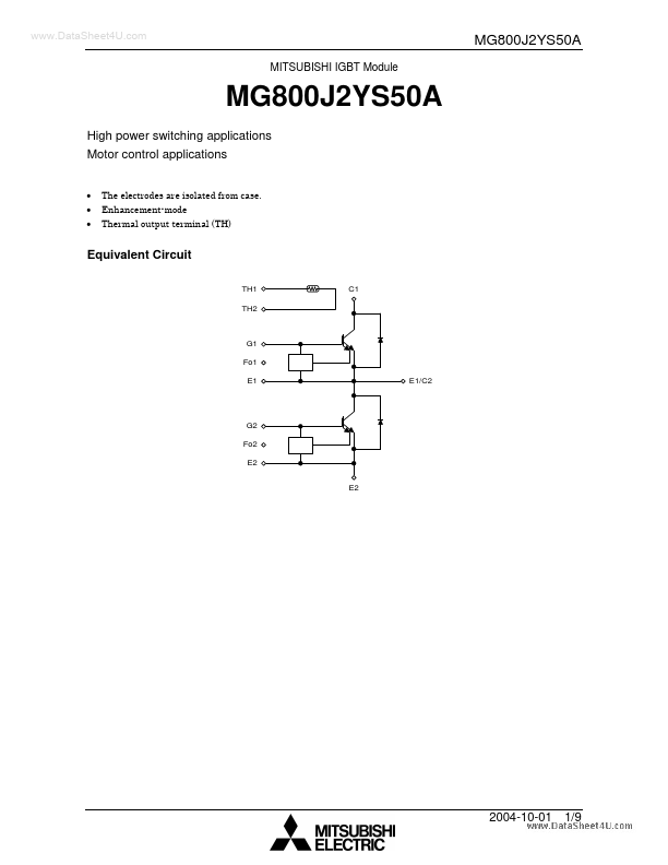
Equivalent Circuit
TH1 TH2 C1
G1 Fo1 E1 E1/C2
G2 Fo2 E2 E2
2004-10-01
1/9
Package Dimensions
Unit: mm
Weight: 680 g (typ.)
2004-10-01
2/9
Maximum Ratings (Ta = 25°C)
Characteristics Collector-emitter voltage Gate-emitter voltage Collector current Forward current Collector power dissipation (Tc = 25°C) Junction temperature Storage temperature range Isolation voltage Terminal: M8 Mounting: M5 DC DC Symbol VCES VGES IC IF PC Tj Tstg VIsol ⎯ ⎯ Rating 600 ±20 800 800 2900 150
- 40~125 2500 (AC 1 min) 10 3 Unit V V A A W °C °C V N- m N- m
Screw torque
Electrical Characteristics (Ta = 25°C)
Characteristics Gate Leakage current Collector cut-off current Gate-emitter cut-off voltage Collector-emitter saturation voltage Input capacitance Gate-emitter voltage Gate resistance Symbol IGES ICES VGE (off) VCE (sat) Cies VGE RG td (on) tr Switching time ton td (off) tf toff Forward voltage VF IF = 800A, VGE = 0V Tj = 25°C Tj = 125°C Inductive load VCC = 300 V IC = 800 A VGE = ±15 V RG = 4.7 Ω (Note) Test Condition VGE = ±20 V, VCE = 0 V VCE = 600 V, VGE = 0 V IC = 800 m A, VCE = 5 V IC = 800 A, VGE = 15 V Tj = 25°C Tj = 125°C Min ⎯ ⎯ 5.0 ⎯ ⎯ ⎯ 13 4.7 ⎯ ⎯ ⎯ ⎯ ⎯ ⎯ ⎯ ⎯ ⎯ ⎯ ⎯ 1600 Typ. ⎯ ⎯ 6.5 2.4 2.6 93000 15 ⎯ 0.3 0.25 0.55 0.85 0.15 1.05 2.3 2.1 ⎯ ⎯ ⎯ ⎯ Max ±10 1 8.0 3.0 3.3 ⎯ 17 15 ⎯ ⎯ ⎯ ⎯ 0.30 ⎯ 3.0 ⎯ 0.5 0.043 C/W 0.056 ⎯ A V µs µs p F V Ω Unit µA m A V V
VCE = 10 V, VGE = 0 V, f = 1 MHz ⎯ ⎯
Reverse recovery time trr
IF = 800 A, VGE =
- 10 V di/dt = 2000 A/µs Transistor stage
Thermal resistance RTC Operating current
Rth (j-c) Diode stage Irtc Tj = 25°C
2004-10-01
3/9
Thermistor
Characteristics Zero power resistance B value Isolation voltage Symbol R25 R25/85 Tc = 25°C Tc = 25°C/Tc = 85°C Tc = 25°C Test Condition Min ⎯ ⎯ 2500...