Motorola 2N6399
Silicon Controlled Rectifiers
| Part No. | 2N6399 |
|---|---|
| Datasheet | 2N6399 Download |
| Manufacturer |  Motorola |
| Description | Silicon Controlled Rectifiers |
| Buy | Stock & Price |

MAXIMUM RATINGS
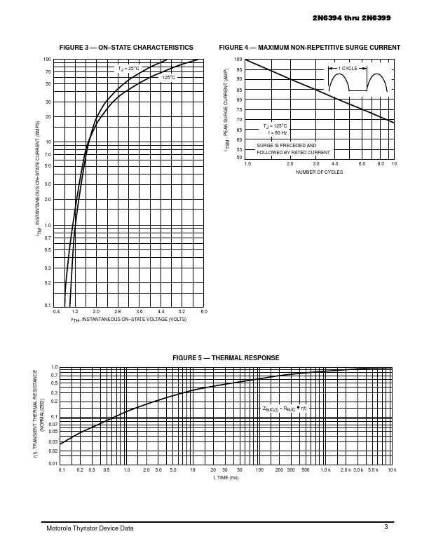
(TJ = 25°C unless otherwise noted.) Rating Peak Repetitive Forward and Reverse Blocking Voltage(1) (Gate Open, TJ = –40 to 125°C) 2N6394 2N6395 2N6397 2N6398 2N6399 RMS On–State Current (TC = 90°C) (All Conduction Angles) Peak Non-Repetitive Surge Current (1/2 Cycle, Sine Wave, 60 Hz, TJ = 125°C) Circuit Fusing (t = 8.3 ms) Forward Peak Power Forward Average Gate Power Forward Peak Gate Current Operating Junction Temperature Range Storage Temperature Range Symbol VDRM, VRRM 50 100 400 600 800 IT(RMS) ITSM I2t PGM PG(AV) IGM TJ Tstg 12 100 40 20 0.5 2 –40 to +125 –40 to +150 Amps Amps A2s Watts Watt Amps °C °C Value Unit Volts THERMAL CHARACTERISTICS Characteristic Thermal Resistance, Junction to Case *Indicates JEDEC Registered Data. 1. VDRM and VRRM for all types can be applied on a continuous basis. Ratings apply for zero or negative gate voltage; however, positive gate voltage shall not be applied concurrent with negative potential on the anode. Blocking voltages shall not be tested with a constant current source such that the voltage ratings of the devices are exceeded.