DESCRIPTION
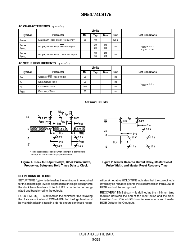
The LS175 consists of four edge-triggered D flip-flops with individual D inputs and Q and Q outputs. The Clock and Master Reset are common. The four flip-flops will store the state of their individual D inputs on the LOW to HIGH Clock (CP) transition, causing individual Q and Q outputs to follow. A LOW input on the Master Reset (MR) will force all Q outputs LOW and Q outputs HIGH independent of Clock or Data inputs. The LS175 is useful for general logic applications where a common Master Reset and Clock are acceptable. TRUTH TABLE Inputs (t = n, MR = H) D L H Outputs (t = n+1) Note 1 Q L H Q H L Note 1: t = n + 1 indicates conditions after next clock. GUARANTEED OPERATING RANGES Symbol VCC TA IOH IOL Supply Voltage Operating Ambient Temperature Range Output Current — High Output Current — Low Parameter 54 74 54 74 54, 74 54 74 Min 4.5 4.75 – 55 0 Typ 5.0 5.0 25 25 Max 5.5 5.25 125 70 – 0.4 4.0 8.0 Unit V °C mA mA DC CHARACTERISTICS OVER OPERATING TEMPERATURE RANGE (unless o... Motorola