DESCRIPTION
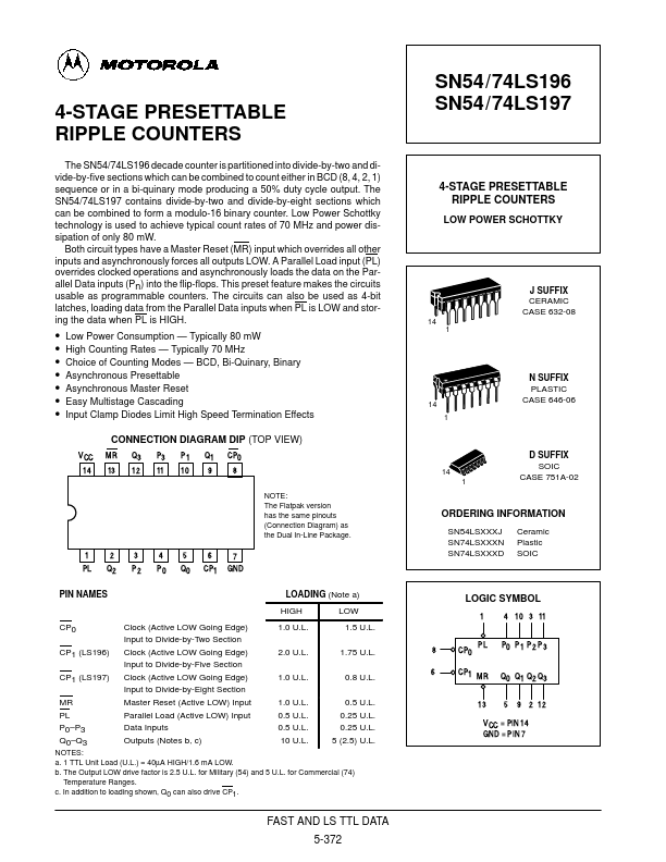
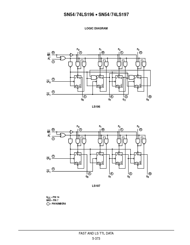
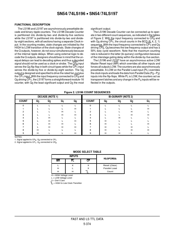
In the counting modes, state changes are initiated by the HIGH to LOW transition of the clock signals. State changes of the Q outputs, however, do not occur simultaneously because of the internal ripple delays. When using external logic to decode the Q outputs, designers should bear in mind that the unequal delays can lead to decoding spikes and thus a decoded signal should not be used as a clock or strobe. The CP0 input serves the Q0 flip-flop in both circuit types while the CP1 input serves the divide-by-five or divide-by-eight section. The Q0 output is designed and specified to drive the rated fan-out plus the CP1 input. With the input frequency connected to CP0 and Q0 driving CP1, the LS197 forms a straightforward module-16 counter, with Q0 the least significant output and Q3 the most significant output. The LS196 Decade Counter can be connected up to operate in two different count sequences, as indicated in the tables of Figure 2. With the input frequency connected to CP0 and with Q0 driving CP1, the circuit counts in the BCD (8, 4, 2, 1) sequence. Motorola