Datasheet4U Logo Datasheet4U.com

MC145159-1 - Serial-Input PLL Frequency Synthesizer

General Description

INPUT PINS OSCin, OSCout Oscillator Input and Oscillator Output (PDIP, SOG Pins 2, 3; SSOP Pins 7, 8) These pins form an on chip reference oscillator when connected to terminals of an external parallel

resonant crystal.

setting capacitors of app

Key Features

  • ch. The divide.
  • by.
  • A/divide.
  • by.
  • N counter latch is loaded, regardless of the contents of the control register, when ENB goes high. The data entry format is shown in Figure 1. ENB Transparent Latch Enable (PDIP, SOG.
  • Pin 13, SSOP.
  • Pin 18) A logic high on this input allows data to be entered into the divide.
  • by.
  • A/divide.
  • by.
  • N latch and, if the control bit is high, into the reference counter latch. Counter programming is.

📥 Download Datasheet

Full PDF Text Transcription (Reference)

The following content is an automatically extracted verbatim text from the original manufacturer datasheet and is provided for reference purposes only.

View original datasheet text
MOTOROLA SEMICONDUCTOR TECHNICAL DATA Serial-Input PLL Frequency Synthesizer with Analog Phase Detector
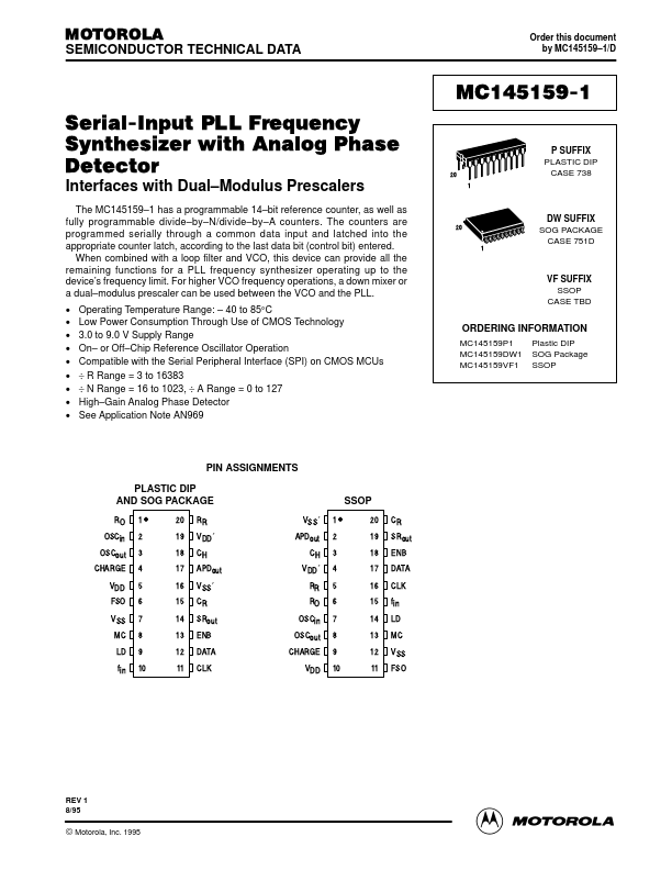
 Interfaces with Dual–Modulus Prescalers The MC145159–1 has a programmable 14–bit reference counter, as well as fully programmable divide–by–N/divide–by–A counters. The counters are programmed serially through a common data input and latched into the appropriate counter latch, according to the last data bit (control bit) entered. When combined with a loop filter and VCO, this device can provide all the remaining functions for a PLL frequency synthesizer operating up to the device’s frequency limit. For higher VCO frequency operations, a down mixer or a dual–modulus prescaler can be used between the VCO and the PLL.