Datasheet4U Logo Datasheet4U.com

MRF19085SR3 - RF Power Field Effect Transistors

Download the MRF19085SR3 datasheet PDF (MRF19085LR3 included). The manufacturer datasheet provides complete specifications, pinout details, electrical characteristics, and typical applications for rf power field effect transistors.

Description

Short Ferrite Bead 51 pF Chip Capacitor 5.1 pF Chip Capacitors 1000 pF Chip Capacitors 0.1 µF Chip Capacitors 0.1 µF Tantalum Surface Mount Capacitor 10 pF Chip Capacitor 10 µF Tantalum Surface Mount Capacitor 22 µF Tantalum Surface Mount Capacitors 1 Turn, 20 AWG, 0.100″ ID Type N Flange Mounts 1.0

Features

  • gure 5. Intermodulation Distortion Products versus Output Power IM3 (dBc), ACPR (dBc), IRL, INPUT RETURN LOSS (dB) 24 η 22 20 18 16 14 12 1930 1940 1950 1960 1970 f,.

📥 Download Datasheet

Note: The manufacturer provides a single datasheet file (MRF19085LR3_Motorola.pdf) that lists specifications for multiple related part numbers.
Other Datasheets by Motorola

Full PDF Text Transcription

Click to expand full text
MOTOROLA SEMICONDUCTOR TECHNICAL DATA Freescale Semiconductor, Inc. Order this document by MRF19085/D
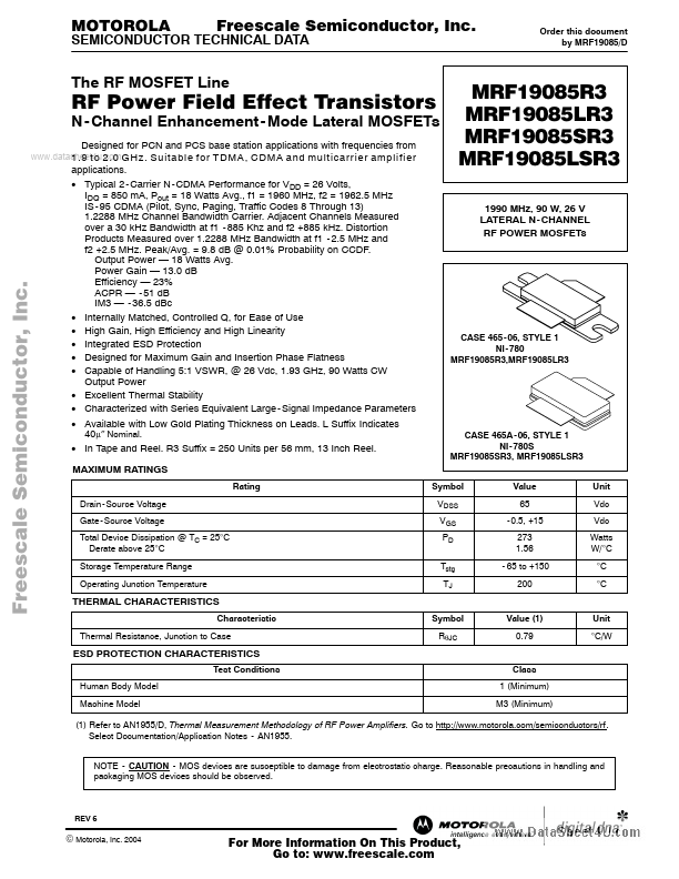
 The RF MOSFET Line RF Power Field Effect Transistors Designed for PCN and PCS base station applications with frequencies from www.datasheet4u.com 1.9 to 2.0 GHz. Suitable for TDMA, CDMA and multicarrier amplifier N - Channel Enhancement - Mode Lateral MOSFETs applications. • Typical 2 - Carrier N - CDMA Performance for VDD = 26 Volts, IDQ = 850 mA, Pout = 18 Watts Avg., f1 = 1960 MHz, f2 = 1962.5 MHz IS - 95 CDMA (Pilot, Sync, Paging, Traffic Codes 8 Through 13) 1.2288 MHz Channel Bandwidth Carrier. Adjacent Channels Measured over a 30 kHz Bandwidth at f1 - 885 Khz and f2 +885 kHz. Distortion Products Measured over 1.2288 MHz Bandwidth at f1 - 2.5 MHz and f2 +2.5 MHz. Peak/Avg. = 9.
Published: |