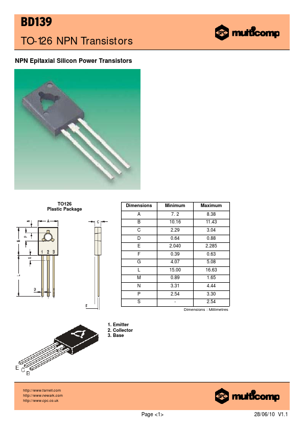
ABSOLUTE MAXIMUM RATINGS
DESCRIPTION
Collector-emitter voltage Collector-emitter voltage (RBE = 1kΩ) Collector-base voltage Emitter base voltage Collector current Collector peak current Base current Power dissipation at Ta = 25°C Derate above 25°C Power dissipation at Tc = 25°C Derate above 25°C Power dissipation at Tc = 70ºC Operating and storage junction Temperature range Symbol VCEO VCER VCBO VEBO IC ICM IB PD PD PD Tj, Tstg BD139 80 100 5.0 1.5 2.0 0.5 1.25 10 12.5 100 8.0 -55 to +150 Unit V A W mW/ºC W mW/ºC W °C Thermal Characteristics Junction to ambient in free air Rth (j-a) 100 Junction to case Rth (j-c) 10 ºC/W ºC/W Electrical characteristics (Tc = 25°C unless specified otherwise) DESCRIPTION
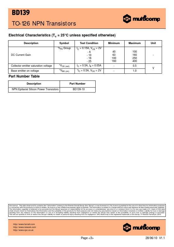
Symbol Test Condition Minimum Maximum Unit Collector emitter sustaining voltage *VCEO (sus) IC = 30mA, IB = 0 BD139 80 V Collector cut off current Emitter cut off current ICBO IEBO VCB = 30V, IE = 0 VCB = 30V, IE = 0, Tc = 125ºC VEB = 5V, IC = 0 0.1 µA 10 DC current gain IC = 0.005A, VCE = 2V 25 *hFE IC = 0.15A, VCE = 2V 40 250 - IC = 0.5A, VCE = 2V 25 *Pulse test: -Pulse width=300ms, duty cycle = 2%. Multicomp