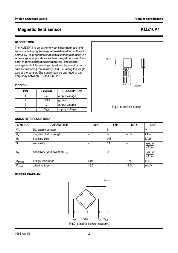
DESCRIPTION
The sensor can be operated at any frequency between DC and 1 MHz. PINNING PIN 1 2 3 4 SYMBOL +VO GND −VO VCC DESCRIPTION
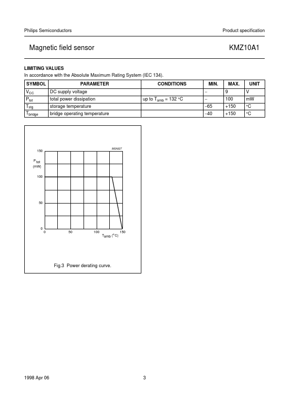
output voltage ground output voltage supply voltage KMZ10A1 y handbook, halfpage Hx H 1 2 3 4 MGL420 Fig.1 Simplified outline. QUICK REFERENCE DATA SYMBOL VCC Hy Hx S Ss Rbridge Voffset PARAMETER DC supply voltage magnetic field strength auxiliary field sensitivity sensitivity (with switched Hx) bridge resistance offset voltage − −0.5 − − − 0.85 −1.5 MIN. 5 − 0.5 14 22 − − TYP. − +0.5 − − − 1.75 +1.5 MAX. V kA/m kA/m mV ⁄ V ---------------kA ⁄ m mV ⁄ V ---------------kA ⁄ m kΩ mV/V UNIT CIRCUIT DIAGRAM handbook, full pagewidth MLC716 1 +VO 2 GND 3 –VO V 4 CC Fig.2 Simplified circuit diagram. 1998 Apr 06 2 Philips Semiconductors Product specification Magnetic field sensor LIMITING VALUES In accordance with the Absolute Maximum Rating System (IEC 134). SYMBOL VCC Ptot Tstg Tbridge PARAMETER DC supply voltage total power dissipation storage temperature bridge operating temperature up to Tamb = 132 °C CONDITIONS − − −65 −40 MIN. NXP Semiconductors