Datasheet4U Logo Datasheet4U.com

NT5TU128M8DE-AD Datasheet 1Gb DDR2 SDRAM

Manufacturer: Nanya

Download the NT5TU128M8DE-AD datasheet PDF. This datasheet also includes the NT5TU256M4GE variant, as both parts are published together in a single manufacturer document.

📥 Download Datasheet

Note: The manufacturer provides a single datasheet file (NT5TU256M4GE-Nanya.pdf) that lists specifications for multiple related part numbers.

General Description

The 1giga-bit (1Gb) Double-Data-Rate-2 (DDR2) DRAMs is a high-speed CMOS Double Data Rate 2 SDRAM containing 1,073,741,824 bits.

It is internally configured as an octal-bank DRAM.

The 1Gb chip is organized as 32Mbit x 4 I/O x 8 bank, 16Mbit x 8 I/O x 8 bank or 8Mbit x 16 I/O x 8 bank device.

Overview

NT5TU256M4GE / NT5TU128M8GE / NT5TU64M16GG 1Gb DDR2 SDRAM Feature 
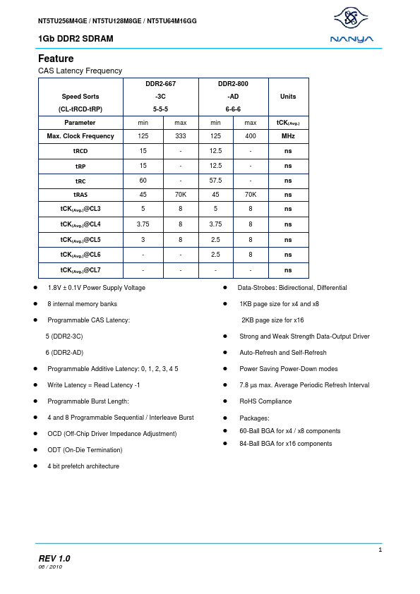
CAS Latency Frequency DDR2-667 Speed Sorts (CL-tRCD-tRP) Parameter Max.

Clock Frequency min 125 15 15 60 45 5 3.75 3 -3C 5-5-5 max 333 70K 8 8 8 min 125 12.5 12.5 57.5 45 5 3.75 2.5 2.5   DDR2-800 -AD 6-6-6 max 400 70K 8 8 8 8 tCK(Avg.) MHz ns ns ns ns ns ns ns ns ns Units tRCD tRP tRC tRAS tCK(Avg.)@CL3 tCK(Avg.)@CL4 tCK(Avg.)@CL5 tCK(Avg.)@CL6 tCK(Avg.)@CL7    1.8V ± 0.1V Power Supply Voltage 8 internal memory banks Programmable CAS Latency: 5 (DDR2-3C) 6 (DDR2-AD) Data-Strobes: Bidirectional, Differential 1KB page size for x4 and x8 2KB page size for x16         Strong and Weak Strength Data-Output Driver Auto-Refresh and Self-Refresh Power Saving Power-Down modes 7.8 µs max.

Average Periodic Refresh Interval RoHS Compliance Packages: 60-Ball BGA for x4 / x8 components 84-Ball BGA for x16 components        Programmable Additive Latency: 0, 1, 2, 3, 4 5 Write Latency = Read Latency -1 Programmable Burst Length: 4 and 8 Programmable Sequential / Interleave Burst OCD (Off-Chip Driver Impedance Adjustment) ODT (On-Die Termination) 4 bit prefetch architecture 1 REV 1.

Key Features

  • (1) posted CAS with additive latency, (2) write latency = read latency -1, (3) normal and weak strength data-output driver, (4) variable data-output impedance adjustment and (5) an ODT (On-Die Termination) function. All of the control and address inputs are synchronized with a pair of externally supplied differential clocks. Inputs are latched at the cross point of differential clocks (CK rising and  falling). All I/Os are synchronized with a single ended DQS or differential DQS pair in a so.