54AC14
Description
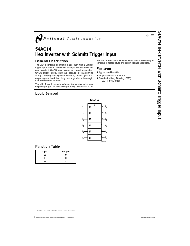
The ’AC14 contains six inverter gates each with a Schmitt trigger input.
Key Features
- n ICC reduced by 50%
- Outputs source/sink 24 mA
- Standard Military Drawing (SMD) — ’AC14: 5962-87624
The ’AC14 contains six inverter gates each with a Schmitt trigger input.
| Part Number | Manufacturer | Description |
|---|---|---|
| 54AC16646 | Texas Instruments | 16-BIT BUS TRANSCEIVERS AND REGISTERS |
| 54AC16620 | Texas Instruments | 16-BIT BUS TRANSCEIVERS |
| 54AC16472 | Texas Instruments | 18-BIT REGISTERED TRANSCIEVERS |
| 54AC11253 | Texas Instruments | DUAL 1-OF-4 DATA SELECTORS/MULTIPLEXERS |
| 54AC11241 | Texas Instruments | OCTAL BUFFERS/LINE DRIVERS |
| 54AC11238 | Texas Instruments | 3-Line to 8-Line Decoders/Demultiplecers |
| 54AC16823 | Texas Instruments | 18-BIT BUS INTERFACE FLIP-FLOPS |
| 54AC16640 | Texas Instruments | 16-BIT BUS TRANSCEIVERS |
| 54AC16374 | Texas Instruments | 16-BIT EDGE-TRIGGERED D-TYPE FLIP-FLOPS |
| 54AC16240 | Texas Instruments | 16-BIT BUS DRIVERS |