9314
Description
The ’9314 is a multifunctional 4-bit latch designed for general purpose storage applications in high speed digital systems All outputs have active pull-up circuitry to provide high capacitance drive and to provide low impedance in both logic states for good noise immunity
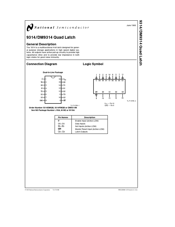
Connection Diagram
Dual-In-Line Package
Logic Symbol
TL F 9788
- 2 TL F 9788
- 1
VCC e Pin 16 GND e Pin 8
Order Number 9314DMQB 9314FMQB or DM9314N See NS Package Number J16A N16E or W16A
Pin Names E D0- D3 S0
- S3 MR Q0- Q3
Description
Enable Input (Active LOW) Data Inputs Set Inputs (Active LOW) Master Reset Input (Active LOW) Latch Outputs
C1995 National Semiconductor Corporation
TL F 9788
RRD-B30M115 Printed in U S A
Absolute Maximum Ratings (Note)
If Military Aerospace specified devices are required please contact the National Semiconductor Sales Office Distributors for availability and specifications Supply Voltage Input Voltage Operating Free Air Temperature Range Military mercial Storage...