DS90CR281
Overview
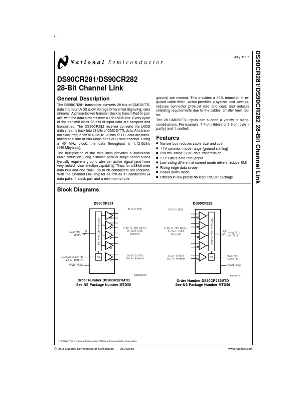
The DS90CR281 transmitter converts 28 bits of CMOS/TTL data into four LVDS (Low Voltage Differential Signaling) data streams. A phase-locked transmit clock is transmitted in parallel with the data streams over a fifth LVDS link.
- n n n n n n
- Narrow bus reduces cable size and cost ± 1V common mode range (ground shifting) 290 mV swing LVDS data transmission 1.12 Gbit/s data throughput Low swing differential current mode drivers reduce EMI Rising edge data strobe Power down mode Offered in low profile 56-lead TSSOP package Block Diagrams