NSBMC290VF
NSBMC290VF is Burst Mode Memory Controller manufactured by National.
NSBMC290-16 -20 -25 -33 Burst Mode Memory Controller
July 1993
NSBMC290 TM -16 -20 -25 -33 Burst Mode Memory Controller
General Description
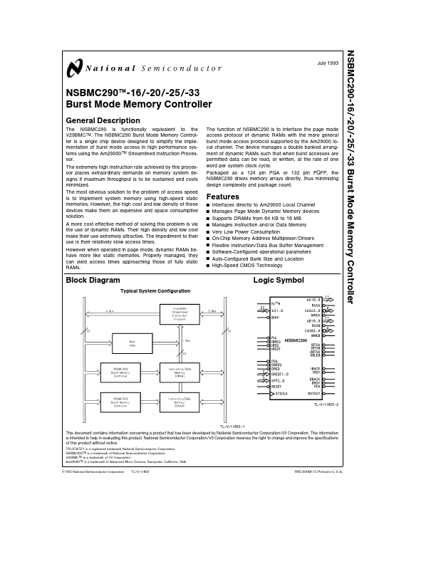
The NSBMC290 is functionally equivalent to the V29BMCTM The NSBMC290 Burst Mode Memory Controller is a single chip device designed to simplify the implementation of burst mode access in high performance systems using the Am29000TM Streamlined Instruction Processor The extremely high instruction rate achieved by this processor places extraordinary demands on memory system designs if maximum throughput is to be sustained and costs minimized The most obvious solution to the problem of access speed is to implement system memory using high-speed static memories However the high cost and low density of these devices make them an expensive and space consumptive solution A more cost effective method of solving this problem is via the use of dynamic RAMs Their high density and low cost make their use extremely attractive The impediment to their use is their relatively slow access times However when operated in page mode dynamic RAMs behave more like static memories Properly managed they can yield access times approaching those of fully static RAMs The function of NSBMC290 is to interface the page mode access protocol of dynamic RAMs with the more general burst mode access protocol supported by the Am29000 local channel The device manages a double banked arrangment of dynamic RAMs such that when burst accesses are permitted data can be read or written at the rate of one word per system clock cycle Packaged as a 124 pin PGA or 132 pin PQFP the NSBMC290 drives memory arrays directly thus minimizing design plexity and package count
Features
Y Y Y Y Y Y Y Y Y Y
Interfaces directly to Am29000 Local Channel Manages Page Mode Dynamic Memory devices Supports DRAMs from 64 KB to 16 MB Manages Instruction and or Data Memory Very Low Power Consumption On-Chip Memory Address Multiplexer Drivers Flexible Instruction Data Bus Buffer Management...