DM74LS166
DM74LS166 is 8-Bit Parallel-In/Serial-Out Shift Registers manufactured by National Semiconductor.
Description
These parallel-in or serial-in serial-out shift registers feature gated clock inputs and an overriding clear input All inputs are buffered to lower the drive requirements to one normalized load and input clamping diodes minimize switching transients to simplify system design The load mode is established by the shift load input When high this input enables the serial data input and couples the eight flip-flops for serial shifting with each clock pulse When low the parallel (broadside) data inputs are enabled and synchronous loading occurs on the next clock pulse During parallel loading serial data flow is inhibited Clocking is acplished on the low-to-high-level edge of the clock pulse through a twoinput NOR gate permitting one input to be used as a clockenable or clock-inhibit function Holding either of the clock inputs high inhibits clocking holding either low enables the other clock input This allows the system clock to be free running and the register can be stopped on mand with the other clock input The clock-inhibit input should be changed to the high level only while the clock input is high A buffered direct clear input overrides all other inputs including the clock and sets all flip-flops to zero
Connection Diagram
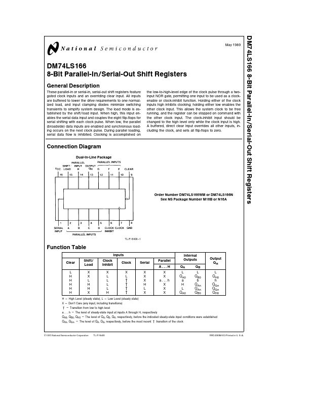
Dual-In-Line Package
Order Number DM74LS166WM or DM74LS166N See NS Package Number M16B or N16A
TL F 6400
- 1
Function Table
Clear
L H H H H H
Shift Load
X X L H H X
Inputs
Clock Inhibit
Clock
XX LL
Lu Lu Lu Hu
Serial
X X X H L X
Parallel
X X ah X X X
Internal Outputs
QA QB
QA0
QB0 ab
H L QA0
QAn QAn QB0
Output QH
L QH0 h QGn QGn QH0
H e High Level (steady state) L e Low Level (steady state) X e Don’t Care (any input including transitions) u e Transition from low to high level a h e The level of steady-state input at inputs A through H respectively QA0 QB0 QH0 e The level of QA QB QH respectively before the indicated steady-state input conditions were established u QAn QGn e The level of QA QG respectively...