MAC15
MAC15 is Triacs Silicon Bidirectional Thyristors manufactured by onsemi.
Features http://onsemi.
- Blocking Voltage to 800 V
- All Diffused and Glass Passivated Junctions for Greater Parameter
- -
- Uniformity and Stability Small, Rugged, Thermowatt Construction for Low Thermal Resistance, High Heat Dissipation and Durability Gate Triggering Guaranteed in Three Modes (MAC15 Series) or Four Modes (MAC15A Series) Pb- Free Packages are Available-
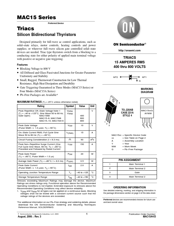
TRIACS 15 AMPERES RMS 400 thru 800 VOLTS
MT2 G MT1
MARKING DIAGRAM
MAXIMUM RATINGS (TJ = 25°C unless otherwise noted)
Rating Peak Repetitive Off- State Voltage Note 1 (TJ =
- 40 to +125°C, Sine Wave 50 to 60 Hz, Gate Open) MAC15A6 MAC15- 8, MAC15A8 MAC15- 10, MAC15A10 Peak Gate Voltage (Pulse Width v 1.0 msec; TC = 90°C) On- State Current RMS; Full Cycle Sine Wave 50 to 60 Hz (TC = +90°C) Circuit Fusing Consideration (t = 8.3 ms) Peak Non- Repetitive Surge Current (One Full Cycle Sine Wave, 60 Hz, TC = +80°C) Preceded and Followed by Rated Current Peak Gate Power (TC = +80°C, Pulse Width = 1.0 ms) Average Gate Power (TC = +80°C, t = 8.3 ms) Peak Gate Current (Pulse Width v 1.0 msec; TC = 90°C) Operating Junction Temperature Range Storage Temperature Range Symbol VDRM, VRRM 400 600 800 VGM IT(RMS) I2t ITSM 10 15 93 150 V A A2s A Value Unit V
4 TO- 220AB CASE 221A STYLE 4 1 MAC15xx G AYWW
MAC15xx xx A Y WW G
= Specific Device Code = See Table on Page 2 = Assembly Location = Year = Work Week = Pb- Free Package
PGM PG(AV) IGM TJ Tstg
20 0.5 2.0
- 40 to +125
- 40 to +150
W W A °C °C 1 2 3 4
PIN ASSIGNMENT
Main Terminal 1 Main Terminal 2 Gate Main Terminal 2
Stresses exceeding Maximum Ratings may damage the device. Maximum Ratings are stress ratings only. Functional operation above the Remended Operating Conditions is not implied. Extended exposure to stresses above the Remended Operating Conditions may affect device reliability. 1. VDRM and VRRM for all types can be applied on a continuous basis. Blocking voltages shall not be tested with a constant current source such that the voltage ratings...